A free Premium account on the FCL.055 website! Read here
Sign up to unlock all our services and 15164 corrected and explained questions.
Question 201-1 : An aircraft is departing from an airport which has an elevation of 2000 ft and the qnh is 1003 hpathe tas is 100 kt the headwind component is 20 kt and the rate of climb is 500 ftmin top of climb is fl 050at what distance from the airport will this be achived ? [ Exam pilot ]
72 nm
Question 201-2 : You are departing from an airport which has an elevation of 1500 ft the qnh is 1003 hpa15 nm away there is a waypoint you are required to pass at an altitude of 7500 ftgiven a groundspeed of 120 kt what is the minimum rate of climb ?
Question 201-3 : An aircraft is flying at fl200the qnh given by a meteorological station at an elevation of 1300ft is 9982 hpa oat = 40°c the elevation of the highest obstacle along the route is 8 000 ftcalculate the aircraft's approximate clearance above the highest obstacle on this route ?
10 500 ft.
Find the qnh altitude 1013 9982 = 148 x 27 = 400 ftaltitude is 19600ft qnhwith aviat 617 computer against altitude pressure = 20 put °c oat = 40then read in the inner circle the altitude 19600 theon the outer circle 18400 true altitude18400 8000ft = 10400ft = approximate clearance over the obstaclefor information 061 general navigation learning objectives states for questions involving height calculation 30 fthpa is to be used unless another figure is specified in the question 9 200 ft. 11 800 ft. 20 200 ft.
Question 201-4 : The qnh given by a station at 2500 ft is 980hpathe elevation of the highest obstacle along a route is 8 000 ft and the oat = isa 10°cwhen an aircraft on route has to descend the minimum indicated altitude qnh on the subscale of the altimeter to maintain a clearance of 2000 ft will be ?
10 400 ft.
We need to be at 10000 ft to avoid the obstacle by 2000 fttemperature correction formula 4° x 10 x 10° = 400 ftthe altimeter over reading in cold air and if we flew exactly at 10000 ft indicated our true altitude would be 9600 ftwe need to cruise at 10000 + 400 = 10400 ft indicated in order to maintain a clearance of 2000 ft10 000 ft. 11 200 ft. 9 700 ft.
Question 201-5 : An aircraft is departing from an airport which has an elevation of 2000 ftoutside temperature is 0°c qnh = 1013 hpait is planned to climb to fl 320 where outside temperature is 60°cthe average cas during climb will be 200 kt compressibility is negligeablemean tas during climb is ?
276 kt.
by convention at the exam easa specification average tas used for climb problems is calculated at the altitude 23 of the cruising altitude temperature is 0°c at 2000 ftapproximately 4° at sea level we 'gain' 2°c per 1000 ft while descending 21000 ft x 2°1000ft = 42°c4°+ 42° = 38°ctemperature is around 38°c at fl210on computer in airspeed window set press alt '21' in front of coat °c ' 38°c' on the outer scale in front of cas 200 kt you can read tas 272 kt289 kt. 244 kt. 331 kt.
Question 201-6 : During visual navigation in freezing conditions after heavy snowfall which of the following landmark will give the best reference for a visual checkpoint ?
A large river.
After heavy snowfall roads will not have been cleared by snow ploughs neither country road or railway a large river may freeze but you will always be able to distinguish its pathA country road. a railway. an electrical line.
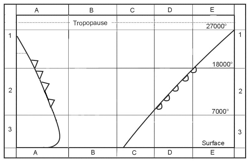
Question 201-7 : During a climb at a constant cas below the tropopause in standard conditions ?
Both tas and mach number will increase.
For those questions use the very simple 'ertm' diagram 1037the cas line is vertical because the question states climb at a constant calibrated airspeed cas ertm for e as r as rectified air speed or cas t as m achTas will decrease but mach number will increase. both tas and mach number will decrease. tas will increase and mach number will decrease.
Question 201-8 : An aircraft is descending down a 12% slope whilst maintaining a gs of 540 kt the rate of descent of the aircraft is approximately ?
Question 201-9 : The departure airfield is at 2000 ft elevation temperature at the field is +20°c qnh 1013 hpa the plan is to climb to fl 290 where outside air temperature is 40°cthe average tas in the climb should be calculated using what fl and temperature ?
Fl 200 with temperature 20°c.
By convention at the exam easa specification average tas used for climb problems is calculated at the altitude 23 of the cruising altitude29000 2000 = 27000 ft23 de 27000 = 18000 ft18000 + 2000 = 20000 ft fl200 température à 20000 ft = 20°c + 20 x 2°c = 20°cFl 290 with temperature -40°c. fl 100 with temperature -10°c. fl 150 with temperature 0°c.
Question 201-10 : The departure is from an airfield at 2000 ft elevation temperature at the field is +20°c qnh 1013 hpa the plan is to climb to fl 290 where outside air temperature is 40°c the cas in the climb is 180 kt compressibility negligiblethe average tas in the climb is ?
249 kt.
1 29000 2000= 27000ft2 27000* 23 = 180003 18000+2000 = 20000 your average alt in climb patern 4 if oat at 2000 alt is +20 so at 20000 will be +20 reference figure 2*18 18 height explanation 2*18 because temp decrease 2 deg per 1000 ft 5 align temp 16 with 22000 ft in th air speed window cr 3 or iwa 11092 and read oposit 180 kt your 249 tas at outer scalethis is only the way to solve tasks like this230 kt. 221 kt. 180 kt.
Question 201-11 : Given wv at arrival aerodrome at 1000 ft amsl is 230°15kt wv at tod at fl 130 is 280°45kt average track after tod is 220° isa conditions descent speed ias = 170 ktfind the gs during the descent ?
163 kt.
At fl130 isa condition ias=170kt => tas=206kt we have wv 280°45kt => drift 12°l so mh=232° to get an average track of 220°so gs= 178kt with computerat 1000ft amsl isa condition ias=170kt => tas=172kt we have wv 230°15kt => drift 1°l so mh=221° to get an average track of 220°so gs= 157kt with computeras a result the average gs for the descent is 157+178 2 = 1675kt155 kt. 180 kt. 174 kt.
Question 201-12 : Given wv at arrival aerodrome at msl is 200°20kt wv at tod at fl 100 is 260°50kt average track after tod is 190°isa conditions descent speed ias = 150 ktfind the gs during the descent ?
135 kt.
145 kt. 120 kt. 150 kt.
Question 201-13 : An aircraft is cruising in fl180 and thereafter descends to ground level the following wind information is given ground level 260°25 ktfl030 270°30 ktfl060 270°35 ktfl090 270°40 ktfl120 280°50 ktfl150 285°55 ktfl180 290°55 ktthe wind to be used for descent calculation is ?
270°40 kt.
By convention average wind velocity used for climb problems is wind velocity at the altitude 23 of the cruising altitudeaverage wind velocity used for descent problems is wind velocity at the altitude 12 of the descent altitude270°/20 kt. 270°/35 kt. 280°/50 kt.
Question 201-14 : The distance between two waypoints is 150 nm to calculate compass heading the pilot used 2°e magnetic variation instead of 2°wassuming that the forecast wv applied what will the off track distance be at the second waypoint ?
10 nm.
For each degree of error that you have at every 60 nm of travel you will be 1 nm off trackyou have 15060 25 nm off track for each degree of errortotal error is 4° from 2°e to 2°w 4° x 25 nm = 10 nmusing goniometric functions tan4° = 150 = tan4° x 150 = 10 nm15 nm. 7 nm. 20 nm.
Question 201-15 : True track 085°groundspeed 180 ktwind 290°30ktvariation 4°ethe aircraft is 15 nm left of track after 12 minuteswhat is the track angle error tke ?
25° l.
Tke = distance off track x 60 distance along tracktke = 15 nm x 60 36 nm = 25°the aircraft has drifted to the left therefore tke is 25° left2.5° r. 1° l. 1° r.
Question 201-16 : With only a visual straight line as visual cue a canal for example this line of position must be selected ?
More or less perpendicular to our track.
More or less parallel to our track. curved across our track. oblique to our track.
Question 201-17 : Given a descending aircraft flies in a straight line to a dme dme 55 nm altitude 33000 ftdme 439 nm altitude 30500 ftm = 072 gs = 525 kt oat = isathe descent gradient is ?
Question 201-18 : The descent gradient of an aircraft with the following data is 60 nm norths of vor xyz fl350 10 nm south of vor xyz fl120 ?
54%.
Total ground distance is 60+10 = 70 nmaltitude difference is 35000 12000 = 23000 ftgradient in % = altitude difference in ft x 100 ground distance in ftground distance in feet 70 nm x 6080 ft = 425600 ftgradient in % = 23000 x 100 425600 = 54%6.4% 7.6%. 4.5%
Question 201-19 : The average tas climbing from 1500 ft to fl180 with a given temperature of isa +15°c a cas of 230 kt and qnh 1032 hpa is ?
283 kt.
by convention at the exam easa specification average tas used for climb problems is calculated at the altitude 23 of the cruising altitude 1032 1013 = 19 hpa19 hpa x 30 ft = 570 ft18000 + 570 = 18570 ft23 of 18570 = 12380 ftto convert cas to tas 1% for each 600 ft and 02% for each degree of isa deviationtas = cas x 12380600 + 02% x 15°c = 230 x 20% + 3% = 2829 kt309 kt. 261 kt. 274 kt.
Question 201-20 : An aircraft is turning on a final approach to intercept a 3° glide slope which is located at an altitude of 700 ft amsl assuming the turn is made at 4 nm from the threshold what is a suitable altitude to intercept the glide slope ?
1916 ft.
1 in 60 rule is a rule of thumb 3° x 4 nm 60 = 02 nm02 nm x 6080 ft = 1216 ftadd 700 ft since we are looking for an altitude = 1216 + 700 = 1916 ft700 ft. 1220 ft. 1290 ft.
Question 201-21 : Given tas 220 ktcruising level fl180track during climb 080°wind at msl 260°25ktwind at fl180 290°55 ktfrom msl to cruising level find the gs during climb ?
262 kt.
We have to use the wind at the altitude 23 of the cruising altitude fl180 x 23 = fl120wind changes by 30° from ground to fl180 an speed increases from 30 ktmean wind at fl120 is 260°+20° and 25kt+20kt = 280°45ktwith your nav computer you will find 262 kt259 kt. 254 kt. 273 kt.
Question 201-22 : An aircraft climbs from ground level to fl180 the following wind information is given ground level 260°25 ktfl030 270°30 ktfl060 270°35 ktfl090 270°40 ktfl120 280°50 ktfl150 285°55 ktfl180 290°55 ktthe wind to be used to solve climb problems eg the calculation of the gs from tas and the track in ?
280°50 kt.
By convention average wind velocity used for climb problems is wind velocity at the altitude 23 of the cruising altitudeaverage wind velocity used for descent problems is wind velocity at the altitude 12 of the descent altitude285°/55 kt. 290°/55 kt. 270°/30 kt.
Question 201-23 : An aircraft descends from fl240 to fl040 for the final approachcas = 220 ktoat = isa +10°cthe average tas in the descent is ?
273 kt.
At the exam average tas used for descent problems is calculated at the altitude 12 of the descent altitudeat fl120 isa temperature = 15°c 2°c x 12 = 9°coat is isa +10°c thus oat is +1°c at fl120on the computer in airspeed window put +1ºc next to fl120 go to cas 220 kt on inner scale and read tas on outer scale 273 kt244 kt. 254 kt. 259 kt.
Question 201-24 : When flying a visual navigation exercise in controlled airspace it is confirmed the aircraft is exactly on track atc instructions are to turn left 30 degrees to avoid conflicting traffic after two minutes they advise 'you are now two miles left of your original track turn right to regain track in 30 ?
034°.
Question issue de ae this question asks about the on in sixty rule this rule states that after 60 nm a drift of 1° corresponds to an off track distance of 1 nm 2° = 2 nm 3° = 3 nm etc the question mentions an off track distance of 2 nm and if you cut the flight distance into half 30 nm instead of 60 nm angle and off track distance must double 30 nm => 4° => 4 nm the question states that the controller wants us to regain our original track after 30 nm so the correction angle should be 4° + 30° = 34°038°. 030°. 042°.
Question 201-25 : An aircraft in cruise at fl120 is cleared to descend to 3000 ftthe distance to go is 25 nmcalculate the descent gradient ?
6%.
We have to descend 9000 ft25 nm in ft is 25 nm x 6000 ftnm = 151900 ft 9000 150000 x 100 = 6%6.3%. 4.7%. 5%.
Question 201-26 : Given descent from 15000 ft to 3000 ft mslglide path angle during descent 3°ground speed 180 kt in 15000 ftground speed 150 kt in 3000 ftcalculate the rate of descent ?
It decreases from 900 ftmin to 750 ftmin.
Rate of descent 3° = ground speed kt x 102at 15000 ft with a ground speed of 180 kt rate of descent = 180 x 102 = 900 ftminapproaching 3000 ft with a decelerating speed to reach 150 kt rate of descent = 150 x 102 = 750 ftmin900 ft/min during the whole descent. 825 ft/min during the whole descent. 750 ft/min during the whole descent.
Question 201-27 : Which formula can be used to calculate the rate of climbdescent rate of climbdescent ftmin = ?
Groundspeed kt x gradient ftnm 60.
We must know the groundspeed to calculate a climbdescent gradientcalculate rate of descent rod on a given glide path angle or gradient using the following rule of thumb formulae rod ftmin = gp degrees x gs nmmin x 100orrod ftmin = gp per cent x gs kt calculate climbdescent gradient ftnm per cent and degrees gs or vertical speed according to the following formula vertical speed ftmin = gs kt x gradient ftnm 60(altitude difference (ft) x 100) / ground difference (ft) climb/descent angle (°) x 100 / 60 arctg (altitude difference (ft) / ground distance covered (ft))
Question 201-28 : The correct formula for climbdescent gradient in % is gradient in % = ?
Vertical distance x 100 ground distance.
Estimate average climbdescent gradient per cent or glide path degrees according to the following rule of thumb gradient in % = vertical distance ft 60 ground distance nm orgradient in % = vertical distance x 100 ground distancegradient in degrees = arctan altitude difference ft ground distance ft orgradient in degrees = vertical distance ft 100 ground distance nm nb these rules of thumb approximate 1 nm to 6 000 ft and are based on the 1 60 ruleHeight difference / (altitude difference x 100). (rate of climb or descent) x ground speed. arctg (altitude difference / ground distance).
Question 201-29 : The correct formula for climbdescent gradient in ° is gradient in ° = ?
Vertical distance ft 100 ground distance nm .
Estimate average climbdescent gradient per cent or glide path degrees according to the following rule of thumb gradient in % = vertical distance ft 60 ground distance nm orgradient in % = vertical distance x 100 ground distancegradient in degrees = arctan altitude difference ft ground distance ft orgradient in degrees = vertical distance ft 100 ground distance nm nb these rules of thumb approximate 1 nm to 6 000 ft and are based on the 1 60 rule(vertical distance (ft) x 60) / ground distance (nm)). (rate of climb or descent) x ground speed. height difference / (altitude difference x 100).
Question 201-30 : An aircraft climbs from ground level to fl180 the following wind information is given ground level 260°25 ktfl030 270°30 ktfl060 270°35 ktfl090 270°40 ktfl120 280°50 ktfl150 285°55 ktfl180 290°55 ktthe wind to be used to solve climb problems eg the calculation of the gs from tas and the track in ?
The wind at fl120.
The wind at fl190. the average wind speed from ground to fl180. the average wind speed from ground to fl120.
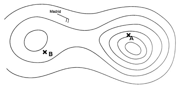
Question 201-31 : An aircraft is flying according the flight log at the annex after 15 minutes of flying with the planned tas and true heading the aircraft is 3 nm south of the intended track and 25 nm ahead of the dead reckoning positionto reach destination b from this position the true heading should be 2504 ?
078°.
15 min 60 = 025h025 x 130 kt gs = 325 nm325 nm + 25nm ahead of dr = 35 nm50 nm dist 35 nm = 15 nmtke = 3 x 6035 and 3 x 6015tke = 5° and 12° ca = 5° + 12° = 17°as we are south of 095° to get back we need to fly more to the north therefore 095 17° = 078°115.° 107°. 090°.
Question 201-32 : The night effect which causes loss of signal and fading resulting in bearing errors from ndb transmissions is due to ?
Skywave distortion of the null position and is maximum at dawn and dusk.
Navigation using an adf to track ndbs is subject to several common effects for night effect radio waves reflected back by the ionosphere can cause signal strength fluctuations 30 to 60 nautical miles 54 to 108 km from the transmitter especially just before sunrise and just after sunset more common on frequencies above 350 khz Interference from other transmissions and is maximum at dusk when east of the ndb. static activity increasing at night particularly in the lower frequency band. the effect of the aurora borealis.
Question 201-33 : Quadrantal errors associated with aircraft automatic direction finding adf equipment are caused by ?
Signal bending by the aircraft metallic surfaces.
quadrantal error ndb signals may reach the receiver aerial directly and also after being reflected by the aircraft body due to electrical circuits and current flowing through them there is an electromagnetic field surrounding the aircraft in general alignment with its bodythis causes the incident radio waves to deflect near the adf receiver aerial the mixed signal affects the null position and the bearing indicated may be with large errorthe maximum effect is at quadrantal relative bearings 045° 135° 225° and 315° relative to headingmodern installations are compensated for this errorSignal bending caused by electrical interference from aircraft wiring. misalignment of the loop aerial. skywave/groundwave contamination.
Question 201-34 : Errors caused by the effect of coastal refraction on bearings at lower altitudes are maximum when the ndb is ?
Inland and the bearing crosses the coast at an acute angle.
coastal refraction or shoreline effect low frequency radio waves will refract or bend near a shoreline especially if they are close to parallel to itleast when bearings normal to coastlineradio waves passing the coastline at small angles suffer refraction due to different conducting and reflecting properties over land and sea a false bearing indication is obtained at aircraft flying over sea and taking bearings from ndb located over land the effect is less for an ndb on coast than one inland and on a bearing 90° to coastline then at an oblique angle hence given the choice use beacon at coast and rely on bearings perpendicular to the coastlineNear the coast and the bearing crosses the coast at right angles. inland and the bearing crosses the coast at right angles. near the coast and the bearing crosses the coast at an acute angle.
Question 201-35 : Transmissions from vor facilities may be adversely affected by ?
Uneven propagation over irregular ground surfaces.
Due to reflections from terrain radials can be bent and lead to wrong or fluctuating indications which is called scalloping Static interference. night effect. quadrantal error.
Question 201-36 : If vor bearing information is used beyond the published protection range errors could be caused by ?
Interference from other transmitters.
Maximum range and altitude published for a vor guaranteed the reception free from harmful interference from other vors when you are within this airspaceNoise from precipitation static exceeding the signal strength of the transmitter. sky wave interference from the same transmitter. sky wave interference from distant transmitters on the same frequency.
Question 201-37 : What is the wavelength of an ndb transmitting on 375 khz ?
800 m.
Wavelength m = 300 f mhz wavelength m = 300000 f khz wavelength = 300000 375 khz = 800 m8000 m. 8 m. 80 m.
Question 201-38 : Phase modulation is ?
A modulation form used in gps where the phase of the carrier wave is reversed.
For the ranging codes and navigation messages to travel from the satellite to the receiver they must be modulated onto a carrier frequency by varying the phase of the signal phase modulation as soon as a data signal will be modulated onto the carrier wave the phase of the carrier wave is reversed by 180° the receiver will detect this reversal and is able to reconstruct the dataA modulation form used in ils where the navigation phase signal changed from 90° or 150°. the cause of an amplitude change of the carrier. the cause of polarisation of the modulated signal.
Question 201-39 : Factors liable to affect most ndbadf system performance and reliability include ?
Static interference night effect absence of failure warning system.
Navigation using an adf to track ndbs is subject to several common effects night effect radio waves reflected back by the ionosphere can cause signal strength fluctuations 30 to 60 nautical miles 54 to 108 km from the transmitter especially just before sunrise and just after sunset more common on frequencies above 350 khz terrain effect high terrain like mountains and cliffs can reflect radio waves giving erroneous readings magnetic deposits can also cause erroneous readings electrical effect or static interference electrical storms and sometimes also electrical interference from a ground based source or from a source within the aircraft can cause the adf needle to deflect towards the electrical source shoreline effect or coastal refraction low frequency radio waves will refract or bend near a shoreline especially if they are close to parallel to it bank effect when the aircraft is banked the needle reading will be offsetit doesn't provide information of failure or malfunctionStatic interference - station interference - latitude error. height error - station interference - mountain effect. coastal refraction - lane slip - mountain effect.
Question 201-40 : Due to doppler effect an apparent decrease in the transmitted frequency which is proportional to the transmitter's velocity will occur when ?
The transmitter moves away from the receiver.
Because the radio signals travel at a constant speed assuming they are not refracted by the atmosphere the receiver can calculate exactly how far away it is from the transmitterspeed is most often calculated by the receiver using the doppler effect which is the process by which the frequency of a signal changes due to the relative motion of the transmitter frequency decreases when the transmitter moves away from the receiverThe transmitter and receiver move towards each other. the transmitter moves toward the receiver. there is no relative movement between the transmitter and the receiver.
Exclusive rights reserved. Reproduction prohibited under penalty of prosecution.