A free Premium account on the FCL.055 website! Read here
Sign up to unlock all our services and 15164 corrected and explained questions.
Question 110-1 : Optimum altitude can be increased progressively during the flight due to the ? [ Training professional ]
Fuel consumption
Question 110-2 : To determine the runway length limited take off mass rltom for an unbalanced field what is the toda to be used given the following data tora 2380 m stopway 1470 m clearway 560 m ?
2940 m.
Icao annex 14volume 1declared distancesa take off run available tora the length of runway declared available and suitable for the ground run of an aeroplane taking offb take off distance available toda the length of the take off run available plus the length of the clearway if providedc accelerate stop distance available asda the length of the take off run available plus the length of the stopway if providedd landing distance available lda the length of runway which is declared available and suitable for the ground run of an aeroplane landingsummary tora = take off run availabletoda = tora + cwy clearway asda = tora + stw stopway lda = tora displaced thresholdtherefore in this case toda = 2380 m + 560 m = 2940 m3850 m 3570 m 4410 m
Question 110-3 : What are the consequences of taking off with anti skid inoperative when field length limited the accelerate stop distance required asdr ?
Increases and v1 decreases.
Antiskid inoperativethe problem to consider is a system failure that is permissible but reduces the aeroplane’s ability to stopthis would typically include antiskid or reverse thrust inoperativeif the antiskid is inoperative braking effectiveness is reduced considerablythis has performance implications for both the rejected take off and landingreduced thrust take offs or operations from contaminated runways are not permitted when antiskid is inoperativehowever an aeroplane’s minimum equipment list mel allows an aeroplane to be dispatched with antiskid inoperative in normal situations but it is restricted to a much lighter take off and landing mass for a given distance availableif the stopping ability of the aeroplane if reduced the fastest speed from which it can stop vstop is slowerhowever to be able to continue the take off with the critical engine failing at this slower speed results in the necessity to reduce the take off massas the stopping ability of aeroplane reduces it needs to increase for the accelerated stop distance availablefor using the whole runway lenght properly v1 decreases for safety reasonIncreases and v1 remains the same. remains the same and v1 remains the same. remains the same and v1 decreases.
Question 110-4 : Assume a take off with a class a aeroplane on a dry runway which of the following values shows the corresponding screen height of the take off distance ?
35 ft.
Easy access rules for air operationsregulation eu no 9652012amc1 catpola210 take off obstacle clearancetake off obstacle clearance a in accordance with the definitions used in preparing the take off distance and take off flight path data provided in the afm 1 the net take off flight path is considered to begin at a height of 35 ft above the runway or clearway at the end of the take off distance determined for the aeroplane in accordance with b below 2 the take off distance is the longest of the following distances i 115% of the distance with all engines operating from the start of the take off to the point at which the aeroplane is 35 ft above the runway or clearway ii the distance from the start of the take off to the point at which the aeroplane is 35 ft above the runway or clearway assuming failure of the critical engine occurs at the point corresponding to the decision speed v1 for a dry runway or iii if the runway is wet or contaminated the distance from the start of the take off to the point at which the aeroplane is 15 ft above the runway or clearway assuming failure of the critical engine occurs at the point corresponding to the decision speed v1 for a wet or contaminated runway class phase screen height a take off dry take off wet 35 ft 15 ft b take off dry take off wet 50 ft a landing dry landing wet 50 ft b landing dry landing wet 50 ft0 ft 50 ft 15 ft
Question 110-5 : What is going to happen with the take off distance required and the accelerate stop distance required if you compare a runway with an upslope to a runway with no slope for a runway with an upslope ?
The take off distance required increases and the accelerate stop distance required increases.
Among others one of the factors affecting the take off and the accelerate stop distance required is the runway slope if the runway slopes downhill the aircraft will be easier to accelerate assisted by a component of the aircraft weight acting downhill and the distance to v1 and to rotate will be reduced while an uphill slope increases the take off distance if the runway slopes downhill it will be harder to stop but the acceleration phase has the greatest effect and overall the accelerate stop distance required decreases if the runway slopes uphill the reverse is true the accelerate stop distance required increasesThe take-off distance required decreases and the accelerate-stop distance required increases. the take-off distance required decreases and the accelerate-stop distance required decreases. the take-off distance required increases and the accelerate-stop distance required decreases.
Question 110-6 : If the field length limited take off mass and v1 were calculated using balanced field lengths the use of any additional clearway in the calculation would cause ?
An increased field length limited take off mass and a reduced v1.
This can be thought of quite intuitively for this question we consider the two most limiting events that can happen during the take off engine failure just before v1 stop scenario and engine failure at v1 go scenario the all engines take off is almost never limitingthe stop scenario sets the length of the asdr accelerate stop distance required the higher the v1 or the higher the weight the greater the asdrthe go scenario sets the length of the todr take off distance required distance to get to screen height engine fails at v1 the lower the v1 or the higher the weight the greater the todr the v1 being lower means that the aircraft has to perform more of its total acceleration with an engine failed which uses more time and runway distancewe often want to maximise the amount of weight that we can take off with this means setting the best possible v1 that allows our asdr and todr to fit exactly within the runway we have got no unused runway realistically we want to calculate it so our asdr equals the asda available and our todr equals the todaon a balanced field the asda available and toda are the same so you end up getting a balanced v1 which is a great starting point and allows for easy calculations this will correspond to a certain flltom field length limiting take off mass which uses up the whole runway in both cases this is also the most effective use of space but it is not always possible to build runways like thisif you were to add some available stopway then with the previous balanced v1 you wouldn't use any of the stopway in the stop scenario however we could decide to use it to squeeze in some extra weight by increasing the v1 to use up all the stopway in the stop scenario and this means that the aircraft is closer to the required climb speed in the go scenario as well which means that it helps both scenarios even without increasing the toda this means we can add weight as we have extra margin in both cases by using a higher v1in the other direction we could add a clearway to the original runway to make it unbalanced in the other way in this case we could use the extra clearway to reduce the v1 as the aircraft has some extra space to get to the screen height now so we can afford to lose the engine earlier in the take off roll and still go this lower v1 means that we won't use up all the runway in the stop case though so we can increase the weight until both required distances match the available distancessummary and extra info if tod = asd v1 = balanced balanced conditionif tod > asd v1 < v1 balanced unbalanced conditionclearway no stopway = higher mass and lower v1 speedif tod < asd v1 > v1 balanced unbalanced conditionstopway no clearway = higher mass and higher v1 speedtora take off run distance available => runway only no stopway or clearway toda take off distance available => tora + clearwayasda accelarate stop distance available => tora + stopwayAn increased obstacle-limited take-off mass with the same v1. an increased field-length-limited take-off mass and an increased v1. an increased obstacle-limited take-off mass and an increased v1.
Question 110-7 : The quick turnaround limit weight qtlw is the maximum landing weight for which ?
There is no minimum ground time required with respect to possible fuse plug melting before executing a subsequent takeoff.
The quick turnaround limit is to do with the wheel fusible alloy plugs that are designed to melt at a predetermined temperature to prevent the tyre exploding when its been subjected to high temperatures caused by heavy brakingthe maximum quick turnaround weight definition is the weight at which after waiting for the maximum amount of time allowable in accordance to your afm for the type and brake category fitted to the airplane involved the fuse melt will not occur or have occurreddifferent times exist as per configuration and can be found in tabular form in your afmfor example 737ng afm refers to 48 67 minutes depending on type of brakes and modelThe landing gear structure will resist between two successive landings. there is no more guarantee for sufficient brake energy absorption in case of a long landing. there is no more guarantee for sufficient brake energy absorption in case of a short landing.
Question 110-8 : Select from the following list of conditions those that must prevail in the second segment of the take off net flight path for a class a aeroplane are 1 undercarriage retracted2 undercarriage extended3 flaps up4 flaps in take off position5 all engines at take off thrust6 operative engine s at take ?
1 4 6 9.
Segments of the take off climbfor a class a aircraft one engine inoperative the to climb is divided into 4 segments 1 the take off flight path starts once the take off is complete at 35 ft with the airplane at v2 with one engine inoperativeon a wet runway the screen height is reduced to 15'operating engines are at takeoff thrust the flapsslats are in takeoff configuration and landing gear retraction is initiated once safely airborne with positive climbthe first segment ends when the landing gear is fully retracted2 begins when the landing gear is fully retractedengines are at takeoff thrust and the flapsslats are in the takeoff configurationthis segment ends at the higher of 400'3 begins at 400' or higher specified acceleration altitudeengines are at takeoff thrust and the aircraft is accelerated in level flightslatsflaps are retracted on speedthe segment ends when aircraft is in clean configuration and the final take off speed has been achievedonce this has happened thrust can be reduced from maximum take off thrust toga to maximum continuous thrust mct4 starts when the flaps are retracted the final segment speed is achieved and the thrust is set to maximum continuous thrust from this point the airplane is climbed to above 1500 ft where the take off flight path endsthe climb gradient for this last stage must not be less than 12% 1º segment 2º segment 3º segment 4º segment starts 35 ft gear up > 400 agl flaps up vfto mct action select gear up climb to > 400 agl retract flaps accelerate to vfto set mct climb to 1500 agl gradient for 2 engines > 0% > 24% na > 12% gradient for 3 engines > 03% > 27% na > 15% gradient for 4 engines > 05% > 30% na > 17%1, 4, 5, 10 1, 5, 8, 10 2, 3, 6, 9
Question 110-9 : A two engine turbojet has to initiate a turn in the second segment of the take off flight path during the turn there is an obstacle that requires a net climb gradient of 20% in order to clear the obstacle the bank angle during the turn is 15° and the flight manual gives a decrement for the turn of ?
33%.
Class a gross gradients 1st segment 2nd segment 3rd segment 4th segment gradient for 2 engines > 0% > 24% > 12% > 12% gradient for 3 engines > 03% > 27% > 15% > 15% gradient for 4 engines > 05% > 30% > 17% > 17% note while third segment is usually flown in level flight the available gradient must be at least equal to that required in final segment 12% during the third segment the high lift devices are retractedeu ops states that the climb gradient to use for the purpose of calculating obstacle clearance must be the net climb gradient net gradient is the gross gradient reduced by a safety factor 08% for 2 engine aircraft 09% for 3 engine aircraft 10% for 4 engine aircraftsolution minimum climb gradient is 2% the turning requires an additional increment of 05% addition of 08% for the net to gross conversion2% + 05% + 08% = 33 %2.8% 3.7% 2.9%
Question 110-10 : For a class a aircraft the net take off flight path is subdivided into various segments which of the following statements is correct ?
The final segment starts at the end of segment 3 with the aircraft in a clean configuration at the final segment climb speed with maximum continuous power set ending at 1500ft or higher if there are distant obstacles to clear.
Segments of the take off climbfor a class a aircraft one engine inoperative the to climb is divided into 4 segments the take off flight path starts once the take off is complete at 35 ft with the airplane at v2 with one engine inoperative on a wet runway the screen height is reduced to 15' operating engines are at takeoff thrust the flapsslats are in takeoff configuration and landing gear retraction is initiated once safely airborne with positive climb the first segment ends when the landing gear is fully retractedbegins when the landing gear is fully retracted engines are at takeoff thrust and the flapsslats are in the takeoff configuration this segment ends at the higher of 400'begins at 400' or higher specified acceleration altitude engines are at takeoff thrust and the aircraft is accelerated in level flight slatsflaps are retracted on speed the segment ends when aircraft is in clean configuration and the final take off speed has been achieved once this has happened thrust can be reduced from maximum take off thrust toga to maximum continuous thrust mctstarts when the flaps are retracted the final segment speed is achieved and the thrust is set to maximum continuous thrust from this point the airplane is climbed to above 1500 ft where the take off flight path ends the climb gradient for this last stage must not be less than 12% 1º segment2º segment3º segment4º segmentstarts35 ftgear up> 400 aglflaps upvftomctactionselect gear upclimb to > 400 aglretract flapsaccelerate to vftoset mctclimb to 1500 aglgradient for 2 engines> 0%> 24%> 12%> 12%gradient for 3 engines> 03%> 27%> 15%> 15%gradient for 4 engines> 05%> 30%> 17%> 17%note while third segment is usually flown in level flight the available gradient must be at least equal to that required in final segment 12% during third segment the high lift devices are retractedThe 3rd segment is completed at the normal flap retraction height and is flown at max continuous thrust the first segment starts at the end of toda where the aircraft should be at 50ft and v2. this segment is flown at v2 whilst the landing gear is retracted the second segment is flown at v3 up to a height of 400ft (flap retraction height)
Question 110-11 : Given that the characteristics of a three engined turbojet aeroplane are as follows thrust = 50 000 newton engineg = 10 ms2drag = 72 569 nminimum steady gradient of climb 2nd segment = 27%sin angle of climb = thrust drag weightthe maximum take off mass under the 2nd segment conditions is… ?
101 596 kg.
1º segment2º segment3º segment4º segmentstarts35 ftgear up> 400 aglflaps upvftomctactionselect gear upclimb to > 400 aglretract flapsaccelerate to vftoset mctclimb to 1500 aglgradient for 2 engines> 0%> 24%> 12%> 12%gradient for 3 engines> 03%> 27%> 15%> 15%gradient for 4 engines> 05%> 30%> 17%> 17%note while third segment is usually flown in level flight the available gradient must be at least equal to that required in final segment 12% during third segment the high lift devices are retractedsolution minimum climb gradient for this exercise is 27% as given by the question according to the regulation we must assume that the critical engine fails at vef speed therefore we only take into consideration the thrust from 2 engines not 3 weight can be calculated using the following formula climb gradient % = thrust – drag ÷ weight27% = 100 000 – 72 569 ÷ w27 100 = 27 431 w0027 = 27 431 ww = 27 431 0027w = 1 015 963 nweight kg = force n ÷ 10 ms2maximum take off mass = 1 015 963 ÷ 10 = 101 5963 kg74 064 kg. 209 064 kg. 286 781 kg.
Question 110-12 : Take off performance data for the ambient conditions show the following limitations with flap 10° selected runway limit 5 270 kgobstacle limit 4 630 kgestimated take off mass is 5 000 kgconsidering a take off with flaps at ?
5° the obstacle limit is increased but the runway limit decreases.
Flap has two effects more flap gives a greater flltom but decreases the cltom and oltom because of the reduced climb gradient less flap reduces the flltom but increases the cltom and oltom because of the improved climb gradientless flaps means better climb gradient after getting airborne due to less drag but increases the ground roll due to less liftthus better climb gardient increases the obstacle limit and increased ground roll decreases the runway limitso this fits with the chosen answer 5 deg increases the obstacle limit and decreases the runway limitthe more flap you've got selected up to the optimum for to improves the field length limitthe downside of flap is that it degrades climb performanceso by selecting 5 flap instead of 10 flap the field limit decreases and the climb limit increases20°, the obstacle limit is increased but the runway limit decreases. 20°, both limitations are increased. 5°, both limitations are increased.
Question 110-13 : The accelerate stop distance on a dry runway considers both the all engine case and the engine failure case the latter is calculated by adding the sum of the distance necessary to accelerate to vef the distance to accelerate to the highest speed reached during the rejected take off ?
The distance to come to a full stop and a distance equivalent to 2 seconds at v1.
Cs 25109 accelerate stop distance a the accelerate stop distance on a dry runway is the greater of the following distances 1 the sum of the distances necessary to – i accelerate the aeroplane from a standing start with all engines operating to vef for take off from a dry runway ii allow the aeroplane to accelerate from vef to the highest speed reached during the rejected take off assuming the critical engine fails at vef and the pilot takes the first action to reject the take off at the v1 for take off from a dry runway and iii come to a full stop on a dry runway from the speed reached as prescribed in sub paragraph a 1 ii of this paragraph plus iv a distance equivalent to 2 seconds at the v1 for take off from a dry runway 2 the sum of the distances necessary to – i accelerate the aeroplane from a standing start with all engines operating to the highest speed reached during the rejected take off assuming the pilot takes the first action to reject the take off at the v1 for take off from a dry runway and ii with all engines still operating come to a full stop on a dry runway from the speed reached as prescribed in subparagraph a 2 i of this paragraph plus iii a distance equivalent to 2 seconds at the v1 for take off from a dry runwayThe distance to come to a full stop, and a distance equivalent to 2 seconds at v1 all multiplied by 1.15. the distance to come to a full stop multiplied by 1.15, and a distance equivalent to 2 seconds at vef. 150% of the distance to come to a full stop, and a distance equivalent to 2 seconds at vef.
Question 110-14 : Select the correct statement with regard to the effect on the ground roll distance if the flap angle setting is increased from 5° to 10° the ground roll distance is ?
Reduced due to the increased lift which reduces the stalling speed and the required take off speed.
Increasing flap angle increases clmax which reduces stalling speed and take off speed this reduces the take off distanceincreasing flap angle increases drag reducing acceleration and increasing the take off distancethe net effect is that take off distance will decrease with increase of flap angle but above a certain flap angle the take off distance will increase againIncreased due to the increased drag, which increases the stalling speed and the required take-off speed. reduced due to the increased lift, which increases the stalling speed, requiring a lower take-off speed. increased due to the reduced lift, which increases the stalling speed and the required take-off speed.
Question 110-15 : A multi engine jet aeroplane is flying at its optimum cruise altitude when an engine fails to minimise the angle of descent the crew should descend at ?
The speed for ldmax maximum lift to drag ratio and reduce weight by jettisoning fuel if possible and required.
In the case of an engine failure the remaining thrust may not sufficient to balance the drag force and the cruise speed cannot be maintained the only solution is to descend to a lower flight altitude where the remaining engine can provide enough thrust to balance the drag and allow level flight as the airplane descends into the lower atmosphere where density is greater the remaining engine can develop more thrust which will equal the drag force this is the gross level off altitude but would give no performance margin so the drift down procedure is continued to a lower altitude the net level off altitudethe level off altitude is determined by the actual air density and also by the actual aircraft mass a higher aircraft mass requires more thrust to balance the drag and consequently a lower level off altitude it can happen that the level off altitude is lower than altitude to clear the obstacles with a safety margin jettison should be considered to lower the aircraft weight increasing the level off altitude also jettison may be required to lower aircraft mass below the aircraft maximum landing massbest glide angle occurs at maximum cl ÷ cd and is unchanged by weight however a lighter aircraft will a have a lower vmd the aircraft will fly at a lower airspeed throw the same glide path maintaining the same gradient of descent with a lower airspeed rod decreases this will allow the aircraft to remain more time in the airThe speed for minimum power required, extending flaps to further increase the lift. 1.32 vmd minimum drag speed and reduce weight by jettisoning fuel if possible and required. vmd minimum drag speed and optimise the angle of descent by increasing lift through the extension of flaps.
Question 110-16 : During a descent with constant mach number below the tropopause in isa conditions how do the tas and cas change tas ?
Increases and cas increases.
Descent at a constant mach number in standard conditionsduring a descent lss will be increasing as temperature increases therefore if mach number is being kept constant the tas must be increasing mach number = taslss during the descent air density increases tas is increasing and cas also increases at a greater rate dynamic pressure = 1 2 v2 similarly in a climb at constant mach number the tas or cas both reduceDecreases, and cas increases. increases, and cas decreases. decreases, and cas decreases.
Question 110-17 : A jet aeroplane is descending en route from cruise altitude at idle thrust if atc requests the crew to descend to a given flight level by a given point such that it requires a steeper descent gradient this could be achieved by… ?
Increasing the airspeed.
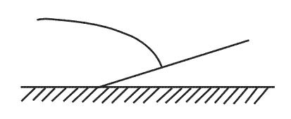
Climb gradient is defined as the ratio of the increase of altitude to horizontal air distance expressed as a percentageabove explanation and figure shows that if you gain speed with nose down attitude thrust levers at idle position you will lose more altitude than you will use thrust assuming that thrust remains at idle the best way to achieve steeper descent is to pitch down which will result in an increase in airspeedReducing the airspeed. extending the flaps. retracting the speed brake.
Question 110-18 : The optimum altitude ?
Increases as mass decreases and is the altitude at which the specific range reaches its maximum.
Optimum altitudeoptimum altitude is defined as the pressure altitude for the best possible fuel efficiency in cruise at which a given thrust setting results in the corresponding maximum range speed at a given weight and speed as a result if flown at a higher or lower pressure altitude than the optimum altitude will decrease the aircraft rangethe optimum altitude is not constant and changes over the period of a long flight as atmospheric conditions and the weight of the aircraft change optimum altitude increases with reducing aircraft weight the drag curve will move down and to the left as the weight decreases through fuel burn which means that the best range speed 132 vmd decreases along with the total drag and as a consequences the aircraft needs to slow down to maintain the best range speed the mach number will decrease and the aircraft will be able to climb a little since it is not limited by the high mach number and high drag the aeroplane maximizes its specific range by remaining at the optimum altitude as it slowly increases it must climb along the green line shown in the attached figure as the optimum altitude increases the specific range increasesIs the altitude at which the specific range reaches its minimum. is the altitude up to which cabin pressure of 8 000 ft can be maintained. decreases as mass decreases.
Question 110-19 : If bleed air systems are used during take off the take off distance is ?
Increased as less thrust is available.
Engine bleed airwhenever bleed air is extracted from an engine and the value of the thrust setting parameter is appropriately reduced the amount of thrust the engine generates is reduced therefore the use of engine bleed air for air conditioningpressurization reduces the airplane’s potential takeoff performance for a given set of runway length temperature and altitude conditions => consequently take off distance increasesadditionally some of the air which passes through the turbine engine is used to cool the combustion chamber and turbine if the air flowing through the engine reduces it will result in a lower cooling capacity and higher exhaust gas temperature egt The same, as it does not on impact engine performance. decreased, due to the lower acceleration. decreased, as more fuel is burnt.
Question 110-20 : A higher pressure altitude at isa temperature ?
Decreases the field length limited take off mass.
Density is determined by pressure temperature and humidity density affects the power or thrust of the engine reduced density will reduce the thrust andor power that the engine can generate therefore acceleration will be less and the maximum tom decreases density affects the tas for a given ias reduced density will increase the true airspeed for a given indicated airspeed getting to a higher tas consequently ground speed can lead to a tyre speed limited take off the angle of the initial climb since there is less thrust andor power in low density the angle of climb will reduce therefore getting to the screen height will require a longer horizontal distance which could not be enough to be clear of obstaclesHas no influence on the allowed take-off mass. decreases the take-off distance. increases the climb limited take-off mass.
Question 110-21 : The second segment begins ?
When landing gear is fully retracted.
Segments of the take off climbfor a class a aircraft the to climb is divided into 4 segments 1 the take off flight path starts once the take off is complete at 35 ft with the airplane at v2 with one engine inoperativeon a wet runway the screen height is reduced to 15'operating engines are at takeoff thrust the flapsslats are in takeoff configuration and landing gear retraction is initiated once safely airborne with positive climbthe first segment ends when the landing gear is fully retracted2 begins when the landing gear is fully retractedengines are at takeoff thrust and the flapsslats are in the takeoff configuration this segment ends at the higher of 400'3 begins at 400' or higher specified acceleration altitudeengines are at takeoff thrust and the aircraft is accelerated in level flight slatsflaps are retracted on speedthe segment ends when aircraft is in clean configuration and the final take off speed has been achievedonce this has happened thrust can be reduced from maximum take off thrust toga to maximum continuous thrust mct4 starts when the flaps are retracted the final segment speed is achieved and the thrust is set to maximum continuous thrustfrom this point the airplane is climbed to above 1500 ft where the take off flight path endsthe climb gradient for this last stage must not be less than 12% 1º segment 2º segment 3º segment 4º segment starts 35 ft gear up > 400 agl flaps up vfto mct action select gear up climb to > 400 agl retract flaps accelerate to vfto set mct climb to 1500 aglWhen acceleration starts from v1 to the speed for flap retraction. when flaps are selected up. when flap retraction begins.
Question 110-22 : For performance class a aeroplanes in commercial air transport operations the take off distance is at least equal to the distance necessary to reach a height of 35 feet on a dry runway with all engines operating multiplied by ?
115.
Class a net take off distance requiredthe take off distance required is the greatest of the following three distances all engines operating the horizontal distance travelled with all engines operating to reach a screen height of 35 ft multiplied by 115 one engine inoperative dry runway the horizontal distance from brp to the point at which the airplane attains 35 ft assuming the critical power unit fails at vef on a dry hard surfaceone engine inoperative wet runway the horizontal distance from brp to the point at which the airplane attains 15 ft assuming the critical power unit fails at vef on a wet or contaminated hard surface achieved in a manner consistent with the achievement of v2 by 35 ft0.95. 1.30. 1.00.
Question 110-23 : What is the effect of using a stopway on the accelerate stop distance required asdr if all other parameters remain constant the asdr… ?
Remains the same.
The accelerate stop distance required will remain the same provided that all other parameters remain constant because it depends on the aircraft's performanceweight etc and we still need such a length in order to stop safely in case of an engine failure the accelerate stop distance available however will increase since the added stopway means that we can have far more runway in case of aborted take offasdr is aircraft performance related determine by the aircraft aerodynamics characteristicsasda is about the runway and the areas associated the runway characteristicsadding a stopway will only increase asdaasda > asdrRemains the same but v1 increases. increases if v1 remains the same. increases and v1 increases.
Question 110-24 : Which of the following speeds is used to describe the situation when the pilot initiates input to the controls intended to lift off ?
Vr.
Rotation speed vr is the speed at which the pilot initiates action to raise the nose gear off the ground with the intention of becoming airbornevr may not be less then decision speed v1Vmcg v1 v2
Question 110-25 : Which of the following options is true as regards to 'reduced thrust ' and 'de rated' take off thrust ?
In a 'reduced thrust' take off the pilot can select the normal configuration any time if needed.
A reduced thrust take off is a take off that is accomplished utilising less thrust than the engines are capable of producing under the existing conditions of temperature and pressure altitude this reduces engine wear a take off thrust which is less than the maximum take off or derated take off thrust is used in this method the thrust for take off is not considered as a take off operating limit which means that maximum take off thrust may be applied at any stage of the take off'operations from contaminated runways are not permissible using 'de rated' take off thrust' incorrect from the boeing 777 fctm reduced takeoff thrust atm may be used for takeoff on a wet runway if approved takeoff performance data for a wet runway is used however reduced takeoff thrust atm is not permitted for takeoff on a runway contaminated with standing water slush snow or ice derated takeoff thrust fixed derate may be used for take off on a wet runway and on a runway contaminated with standing water slush snow or ice 'for a 'reduced thrust' take off there are certain 'limitations' that can be increased' incorrect limitations should not be ignored and no exemptions shall be made in order to decrease engine wear'the 'de rated ' take off thrust must be at least 75% of the normal take off thrust' incorrect the reduced take off thrust setting is at least 75 percent of the take off thrustThe 'de-rated ' take-off thrust must be at least 75% of the (normal take-off) thrust. operations from contaminated runways are not permissible using 'de-rated' take-off thrust. for a 'reduced thrust' take-off there are certain 'limitation' that can be inreased.
Question 110-26 : In case of landing on a flooded runway and in stormy conditions you will 1 increase your approach speed 2 land firmly in order to obtain a firm contact of the wheels with the runway and immediately land your nose gear 3 decrease your approach speed 4 use systematically all the lift dumper devices 5 ?
1 2 47.
Heavy rain will form a film of water on an aircraft and increase its weight slightly maybe as much as 1 2% this in itself will increase stall speed hence there is a theoretical argument for increasing approach speed in heavy rainon wetflooded or slush covered runways the tire may hydroplane which reduces the braking forces between the tire and runway significantly therefore in such conditions a positive firm not hard landing is required to break through the layers of water on the runway thus minimising the risk of aquaplaning a greaser of a landing is most certainly not the answer because you will only add to the risk of aquaplaning furthermore wheel spin up can be delayed on slippery runways which affects the proper functioning of the antiskid system and the deployment of ground spoilerswhen on the runway you should apply reverse thrust and lift dumper devices the lift dumpers are basically ground spoilers that are used to dump lift which consequently puts the weight down on the wheels and increases controlbraking action2, 3, 4 3, 5, 6 1, 4, 5, 6
Question 110-27 : In the ops regulations a runway is referred to as contaminated when more than 25 % of the required runway surface is covered with the one of the following elements 1 a water film sufficiently thick to give a shiny appearance to the runway 2 a water film or loose or slushy snow equivalent to more ?
2 3 4.
Easa air opsannex i to viii contaminated runway a runway is considered to be contaminated when more than 25% of the runway surface area whether in isolated areas or not within the required length and width being used is covered by the following a surface water more than 3 mm 0125 in deep or by slush or loose snow equivalent to more than 3 mm 0125 in of water b snow which has been compressed into a solid mass which resists further compression and will hold together or break into lumps if picked up compacted snow or c ice including wet ice damp runway a runway is considered damp when the surface is not dry but when the moisture on it does not give it a shiny appearance dry runway a dry runway is one which is neither wet nor contaminated and includes those paved runways which have been specially prepared with grooves or porous pavement and maintained to retain effectively dry braking action even when moisture is present wet runway a runway is considered wet when the runway surface is covered with water or equivalent less than specified in subparagraph a 2 above or when there is sufficient moisture on the runway surface to cause it to appear reflective but without significant areas of standing water1, 2, 3, 4 1, 3, 4, 5 1, 3, 4
Question 110-28 : Is the use of toga still possible when the fms has been set up for a reduced thrust take off ?
Yes toga is always possible during a reduced thrust take off.
A reduced thrust take off is a take off that is accomplished utilising less thrust than the engines are capable of producing under the existing conditions of temperature and pressure altitude the primary advantage of the use of reduced take off thrust is cost savings through increased engine life and reduced overhaul costs secondary advantages include fuel savingshowever even when the fms has been set up for a reduced thrust take off toga will still be available using maximum take off thrust set toga will result in an increased take off performance therefore in order to increase the safety margin in case of any system failure emergency or adverse weather conditions the pilot can decide to proceed with the normal configuration with the maximum take off thrust set toga Toga cannot be selected anymore once the take-off power is set. yes, toga is always available when doing a reduced thrust and/or a derated take-off. toga can only be selected above 100 kt once positive directional control has been established.
Question 110-29 : What happens to the long range cruise speed when descending below the optimum altitude for a jet aeroplane ?
Mach number decreases.
Long range cruise lrc speed is the traditional cruise speed it has been historically defined as the speed above maximum range cruise mrc speed with a 1 percent decrease in fuel mileage but a 3 5% gain in cruise velocityit is derived as an eas from the total drag curve at 137 vmd take a look at the attached graph if 'e' is kept constant mach number for lrc increases as altitude increases likewise it will decrease with decreasing altitudeMach number increases. mach number remains constant. eas increases.
Question 110-30 : Impingement drag is… ?
Wheels causing water to hit the airframe.
Fluid contaminants contribute to stopping force by resisting forward movement of the wheels ie causing displacement drag and creating spray that strikes the landing gear and airframe ie causing impingement drag Water striking the tail. water being displaced by the tyres. water being ingested into the engines.
Question 110-31 : Which of the following runway contaminants are given in a snowtam ?
Slush ice compacted snow standing water.
The contaminants listed in a snowtam are 1 — damp 2 — wet or water patches 3 — rime or frost covered depth normally less than 1 mm 4 — dry snow 5 — wet snow 6 — slush 7 — ice 8 — compacted or rolled snow 9 — frozen ruts or ridgesCompacted snow, frozen ruts, slush, hailstones. powder snow, slush, ice, compacted snow, frozen ruts. frozen ruts, ice pellets, slush, wet snow, compacted snow.
Question 110-32 : The formula 9 x tyre pressure is used to determine ?
Dynamic hydroplaning.
Dynamic hydroplaning rotating wheel aborted take off occurs when there is standing water or slush on the runway deeper than the tread depth of the tyres a wedge of water builds up lifting the tires away from the runway surface the speed of the airplane the depth of the water and the air pressure in the tires are some of the factors that affect dynamic hydroplaning 9 x tyre pressure psi viscous hydroplaning stopped wheel initial spin up on touchdown can occur when oil or accumulated rubber combines with water on a runway it forms an impenetrable layer of liquid your tires can’t break through this is especially problematic on smooth runways and it can occur on just a thin film of water viscous hydroplaning typically occurs in the touchdown zone of the runway where you get a build up of black rubber deposit 77 x tyre pressure psiViscous hydroplaning. maximum vr. minimum pcn required for taxi.
Question 110-33 : What is the result of an increase in air density ?
V2 increases.
Air density has a profound effect on the thrust produced the volume of the air flowing through the engine is relatively fixed for any particular rpm by the size and geometry of the inlet duct system but since the thrust is determined by mass not the volume of air any increases in its density increases the mass and thus the thrustvmca is defined as the minimum speed whilst in the air that directional control can be maintained with one engine inoperative critical engine on two engine aerolanes operating engine s at takeoff power and a maximum of 5 degrees of bank towards the good engine s the operative engine requires more rudder authority to maintain directional stability due to the increase in thrust the airplane maintains directional authority at a higher indicated airspeed therefore vmca increases with increasing air density v2 speed is always greater than vmca therefore v2 must also increaseV2 increases then decreases. v2 decreases. vsr decreases then increases.
Question 110-34 : An operator shall ensure that the net take off flight path clears all obstacles the semi width of the obstacle corridor at the distance d from the end of the toda for an aircraft with a wingspan of less than 60 m is at least ?
12 wingspan + 60 m + 0125d.
Obstacle accountability areaobstacles are considered if they lie in an area called the 'obstacle accountability area'for aircraft with a wing span of less than 60m semi width of such area is calculated 60 m + 0125 x d + ½ wingspan if the flight path requires a change of track direction between 0 and 15 deg then the area reaches a maximum semi width of 300m if the flight path requires a change of track direction above 15 deg then the area reaches a maximum semi width of 600mfor aircraft with a wing span of more than 60m semi width of such area is calculated 90 m + 0125 × dd = horizontal distance travelled from the end of toda or tod2x wingspan + 90 m + 0.125d 1/2 wingspan + 90 m + 0.125d 2x wingspan + 60 m + 0.125d
Question 110-35 : In the landing roll when can the pilot apply the brakes 1 when both main gears touch the ground 2 when at least one main gear has contact with runway 3 when both main gears are on the ground and provided that the nose gear can be lowered in a controlled manner permitting it to touch down safely 4 ?
3 and 4.
Cs 25 amc 25125 c landing1 during measured landings if the brakes can be consistently applied in a manner permitting the nose gear to touch down safely the brakes may be applied with only the main wheels firmly on the ground otherwise the brakes should not be applied until all wheels are firmly on the ground2 this is not intended to prevent operation in the normal way of automatic braking systems which for instance permit brakes to be selected on before touchdown1 and 2. 1, 3 and 4. 1, 2 and 4.
Question 110-36 : What is the effect of impingement drag and displacement drag on take off and rto distances ?
Negative positive.
Fluid contaminants contribute to stopping force by resisting forward movement of the wheels ie causing displacement drag and creating spray that strikes the landing gear and airframe ie causing impingement drag a slower acceleration due to an increase in drag as the aircraft tyres plow through the contaminant displacement drag and a spray of contamination is created which strikes the landing gear and airframe impingement drag can be expected => it has a negative effect on take off distance and positive effect on rejected take off distancenote this question has raised some debate we assume that easa refers to the rejected take off distance only rather than the asdr the runway required to accelerate to vr and bring the aircraft to a complete stop Negative - negative. positive – negative. positive - positive.
Question 110-37 : For which hydroplaning speed do you use a factor of 9 ?
Dynamic.
Dynamic hydroplaning rotating wheel aborted take off occurs when there is standing water or slush on the runway deeper than the tread depth of the tyres a wedge of water builds up lifting the tires away from the runway surface the speed of the airplane the depth of the water and the air pressure in the tires are some of the factors that affect dynamic hydroplaning 9 x tyre pressure psi viscous hydroplaning stopped wheel initial spin up on touchdown can occur when oil or accumulated rubber combines with water on a runway it forms an impenetrable layer of liquid your tires can’t break through this is especially problematic on smooth runways and it can occur on just a thin film of water viscous hydroplaning typically occurs in the touchdown zone of the runway where you get a build up of black rubber deposit 77 x tyre pressure psiViscous. reverted rubber hydroplaning. used only when anti/skid is inoperative.
Question 110-38 : An aircraft is flying at vmcl following an engine failure does the aircraft have sufficient performance for both approach and go around ?
Yes the performance is good enough.
Vmcl is the minimum control speed during the approach and landing it covers the situation where an aircraft is making an approach in trim and with all engines operating and then has to initiate a go around at which point one engine fails the immediate situation is that the live engine is at full go around power and producing powerful yawing moments before the pilot has had time to re trim the aircraft for that conditionscs 25149 minimum control speed f see amc 25149 f vmcl the minimum control speed during approach and landing with all engines operating is the calibrated airspeed at which when the critical engine is suddenly made inoperative it is possible to maintain control of the aeroplane with that engine still inoperative and maintain straight flight with an angle of bank of not more than 5º vmcl must be established with – 1 the aeroplane in the most critical configuration or at the option of the applicant each configuration for approach and landing with all engines operating 2 the most unfavourable centre of gravity 3 the aeroplane trimmed for approach with all engines operating 4 the most unfavourable weight or at the option of the applicant as a function of weight 5 for propeller aeroplanes the propeller of the inoperative engine in the position it achieves without pilot action assuming the engine fails while at the power or thrust necessary to maintain a 3 degree approach path angle and 6 go around power or thrust setting on the operating engine s No, the aircraft is not able to continue the approach. only the approach can be flown. go-around can only be flown over flat terrain.
Question 110-39 : In case of contaminated runways wind limitations may apply where are those limitations found ?
Part b of the operations manual.
Easa air ops amc3 oromlr100 operations manual – general b aircraft operating matters — type related 1 limitations 11 a description of the certified limitations and the applicable operational limitations should include the following a certification status eg easa supplemental type certificate environmental certification etc b passenger seating configuration for each aircraft type including a pictorial presentation c types of operation that are approved eg vfrifr cat iiiii rnp flights in known icing conditions etc d crew composition e mass and centre of gravity f speed limitations g flight envelope s h wind limits including operations on contaminated runways i performance limitations for applicable configurations j runway slope k for aeroplanes limitations on wet or contaminated runways l airframe contamination m system limitationsoromlr101 operations manual – structure for commercial air transport except for operations with single engined propeller driven aeroplanes with an mopsc of 5 or less or single engined non complex helicopters with an mopsc of 5 or less taking off and landing at the same aerodrome or operating site under vfr by day the main structure of the om shall be as follows a part a generalbasic comprising all non type related operational policies instructions and procedures b part b aircraft operating matters comprising all type related instructions and procedures taking into account differences between typesclasses variants or individual aircraft used by the operator c part c commercial air transport operations comprising routerolearea and aerodrome operating site instructions and information d part d training comprising all training instructions for personnel required for a safe operationPart a of the operations manual part c of the operations manual part d of the operations manual
Question 110-40 : Where are the procedures associated with take off and landing on contaminated runways found ?
Part b of the operations manual.
Easa air opsamc3 oromlr100 operations manual – generalb aircraft operating matters — type related2 normal proceduresthe normal procedures and duties assigned to the crew the appropriate checklists the system for their use and a statement covering the necessary coordination procedures between flight and cabinother crew members the normal procedures and duties should include the following a pre flight b pre departure c altimeter setting and checking d taxi take off and climb e noise abatement f cruise and descent g approach landing preparation and briefing h vfr approach i ifr approach j visual approach and circling k missed approach l normal landing m post landing n for aeroplanes operations on wet and contaminated runwaysoromlr101 operations manual – structure for commercial air transportexcept for operations with single engined propeller driven aeroplanes with an mopsc of 5 or less or single engined non complex helicopters with an mopsc of 5 or less taking off and landing at the same aerodrome or operating site under vfr by day the main structure of the om shall be as follows a part a generalbasic comprising all non type related operational policies instructions and procedures b part b aircraft operating matters comprising all type related instructions and procedures taking into account differences between typesclasses variants or individual aircraft used by the operator c part c commercial air transport operations comprising routerolearea and aerodrome operating site instructions and information d part d training comprising all training instructions for personnel required for a safe operationPart c of the operations manual part a of the operations manual part d of the operations manual
Exclusive rights reserved. Reproduction prohibited under penalty of prosecution.