A free Premium account on the FCL.055 website! Read here
Sign up to unlock all our services and 15164 corrected and explained questions.
Question 200-1 : Complete line 4 of the 'flight navigation log' positions 'g' to 'h' what is the hdg° m and eta 2497 ? [ Exam pilot ]
Hdg 344° eta 1336 utc
Question 200-2 : Complete line 5 of the 'flight navigation log' positions 'j' to 'k' what is the hdg° m and eta 2497 ?
Hdg 337° eta 1422 utc.
2496Hdg 320° - eta 1412 utc. hdg 337° - eta 1322 utc. hdg 320° - eta 1432 utc.
Question 200-3 : Complete line 6 of the flight navigation log positions l to m what is the hdg° m and eta 2497 ?
Hdg 075° eta 1502 utc.
2496you have to find tas set 55°c in the airspeed window next to mkt read on the outer main scale in front of 084 a tas of 485 ktbelow center dot set tas 485 kt under index set true course 070° with the rotative scale set the wind 020°60kt read below 60 kt a 6° right drifttrue heading = 070° 6° = 064°gs is 441 kt after having set the true heading on the computermagnetic heading = 064° + 11° variation = 075° 495441 x60 = 67 minutesHdg 064° - eta 1449 utc. hdg 075° - eta 1452 utc. hdg 070° - eta 1459 utc.
Question 200-4 : Given tas = 197 kt true course = 240° wv = 18030ktdescent is initiated at fl 220 and completed at fl 40distance to be covered during descent is 39 nmwhat is the approximate rate of descent ?
1400 ftmin.
Using flight computer you will get gs = 182 ktdistance = rate x time39 nm = 182 x timet = 39182 = 0214h > 128 min total time of descent 22000 ft 4000 ft = 18000 ft height to be flown in descent 18000 128 min = 1406 ftmin800 ft/min. 950 ft/min. 1500 ft/min.
Question 200-5 : Given ils glide path angle = 35° ground speed = 150 ktwhat is the approximate rate of descent ?
900 ftmin.
1 in 60 rule is a rule of thumb 35 x 150 x 100 60 = 875 ftmin350 ft/min. 700 ft/min. 300 ft/min.
Question 200-6 : Given aircraft height 2500 ft ils gp angle 3° at what approximate distance from thr can you expect to capture the gp ?
83 nm.
Distance= height x 60 angle° distance= 2500x603° distance= 50000 ft then divide by 6080 as 1nm=6080 ft 7.0 nm. 13.1 nm. 14.5 nm.
Question 200-7 : An island appears 60° to the left of the centre line on an airborne weather radar display what is the true bearing of the aircraft from the island if at the time of observation the aircraft was on a magnetic heading mh of 276° with the magnetic variation 10°e ?
046°.
276° mh + 10°e = 286° th 286° 60° = 226° th to the island to get from the island simply reverse it 226° 180° = 046°086°. 226°. 026°.
Question 200-8 : An island appears 45° to the right of the centre line on an airborne weather radar display what is the true bearing of the aircraft from the island if at the time of observation the aircraft was on a magnetic heading mh of 215° with the magnetic variation 21°w ?
059°.
215° mh 21°w = 194° th 194° + 45° = 239° th to the island to get from the island simply reverse it 239° 180° = 059°101°. 239°. 329°.
Question 200-9 : An island appears 30° to the right of the centre line on an airborne weather radar display what is the true bearing of the aircraft from the island if at the time of observation the aircraft was on a magnetic heading mh of 355° with the magnetic variation var 15°e ?
220°.
355° mh + 15°e = 010° th 010° + 30° = 040° th to the island to get from the island simply reverse it 040° + 180° = 220°160°. 130°. 190°.
Question 200-10 : An island appears 30° to the left of the centre line on an airborne weather radar display what is the true bearing of the aircraft from the island if at the time of observation the aircraft was on a magnetic heading mh of 020° with the magnetic variation var 25°w ?
145°.
020° mh 25°w = 355° th island is on the left so 355° 30° = 325°true bearing from the island so 325° 180° = 145°325°. 205°. 195°.
Question 200-11 : Given an aircraft is flying a track of 255° m 2254 utc it crosses radial 360° from a vor station 2300 utc it crosses radial 330° from the same station at 2300 utc the distance between the aircraft and the station is ?
The same as it was at 2254 utc.
1724this is an isosceles trianglethe first angle at 22 54 is 255° 180° = 75°the second angle at the vor is 30°the last one = 180° 75°+30° = 75°Greater than it was at 2254 utc randomly different than it was at 2254 utc less than it was at 2254 utc
Question 200-12 : The distance between two waypoints is 200 nm to calculate compass heading the pilot used 2°e magnetic variation instead of 2°wassuming that the forecast wv applied what will the off track distance be at the second waypoint ?
14 nm.
For each degree of error that you have at every 60 nm of travel you will be 1 nm off trackyou have 20060 333 nm off track for each degree of errortotal error is 4° from 2°e to 2°w 4° x 333 nm = 1333 nmusing goniometric functions tan4° = 200 = tan4° x 200 = 1399 nm7 nm. 0 nm. 21 nm.
Question 200-13 : Given eta to cross a meridian is 2100 utcgs is 441 kttas is 491 ktat 2010 utc atc requests a speed reduction to cross the meridian at 2105 utcthe reduction to tas will be approximately ?
40 kt.
At 20h10 the airplane is at 50 minutes of the meridian with a speed of 441 kt thus at a distance of 3675 nm 44160 x 50 now it has to travel 3675 nm in 55 minutes 3675 55 x 60 = 401 kttas reduction is 441 401 = 40 kt90 kt. 75 kt. 60 kt.
Question 200-14 : The flight log gives the following data 'true track drift true heading magnetic variation magnetic heading compass deviation compass heading' the right solution in the same order is ?
119° 3°l 122° 2°e 120° +4° 116°.
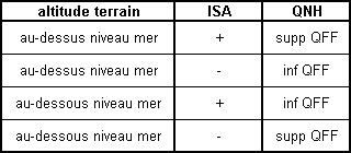
2498use this wonderful table for those questions115°, 5°r, 120°, 3°w, 123°, +2°, 121° 117°, 4°l, 121°, 1°e, 122°, -3°, 119° 125°, 2°r, 123°, 2°w, 121°, -4°, 117°
Question 200-15 : At 0020 utc an aircraft is crossing the 310° radial at 40 nm of a vordme station at 0035 utc the radial is 040° and dme distance is 40 nm magnetic variation is zerothe true track and ground speed are ?
085° 226 kt.
Draw the situation 2499it is a isosceles triangle with at least two equal sidesthe angle at the vor is 90° and the other two angles are 45°at 00 20 the bearing from the aircraft to the vor is 310° 180° = 130°track is 130° 45° = 085°it is not mandatory to calculate the groundspeed but you can use pythagoras 40² + 40² = distance between position at 00 20 and postion at 00 35 ²distance is = 56567 nm56 nm covered in 15 minutes 5656715 x60 = 226 kt090° - 232 kt. 080° - 226 kt. 088° - 232 kt.
Question 200-16 : Given tas is 120 ktata 'x' 1232 utceta 'y' 1247 utcata 'y' is 1250 utcwhat is eta 'z' 2500 ?
1302 utc.
X to y = 30 nm in 18 minutes from 12h32 to 12h50 = 100 kt ground speedy to z = 20 nm at 100 kt = 12 minutes12h50 + 12 minutes = 13h021257 utc. 1300 utc. 1303 utc.
Question 200-17 : Given fl120 oat is isa standard cas is 200 kt track is 222° m heading is 215° m variation is 15°wtime to fly 105 nm is 21 minwhat is the wind ?
050° t 70 kt.
Oat at fl120 is 15° 2° x 12 = 9°c 2501magnetic heading is 215° variation is 15°w = true heading is 200°our magnetic track is 222° minus 15°w = true track is 207° 105 nm 21 min x 60 = 300 kt ground speedon the computer under centre dot set tas 239 kt under index set true heading 200° mark the point where drift 7°right crosses the ground speed 300 kt 2502wind is 050°70 kt040°(t) / 105 kt. 055°(t) / 105 kt. 065°(t) / 70 kt.
Question 200-18 : A useful method of a pilot resolving during a visual flight any uncertainty in the aircraft's position is to maintain visual contact with the ground and ?
Set heading towards a line feature such as a coastline motorway river or railway.
Fly the reverse of the heading being flown prior to becoming uncertain until a pinpoint is obtained fly expanding circles until a pinpoint is obtained fly reverse headings and associated timings until the point of departure is regained
Question 200-19 : An aircraft is descending down a 6% slope whilst maintaining a ground speed of 300 ktthe rate of descent of the aircraft is approximately ?
1800 ftmin.
1 nm = 6080 ft6% ==> 006 300 kt x 6080 ft 60 min x 006 = 1824 ftmin10800 ft/min. 3600 ft/min. 900 ft/min.
Question 200-20 : An aircraft is flying according the flight log at the annexafter 15 minutes of flying with the planned tas and true heading the aircraft is 3 nm north of the intended track and 25 nm ahead of the dead reckoning positionto reach destination b from this position the true heading should be 2516 ?
258°.
251715 min 60 = 025h025 x 130 kt gs = 325 nm325 nm + 25 nm ahead of dr = 35 nm50 nm distance 35 nm = 15 nmtke = 3 x 6035 and correction angle = 3 x 6015tke = 5° and 12° ca = 5° + 12° = 17°as we are north of 275° to get back we need to fly more to the south therefore minus 17° so 275° 17° = 258°292°. 270°. 253°.
Question 200-21 : An island is observed to be 30° to the right of the nose of the aircraft the aircraft heading is 290° m variation 10° e the bearing ° t from the aircraft to the island is ?
330°.
Magnetic heading 290°variation east magnetic least magnetic heading = true heading 10°etrue heading = magnetic heading + 10°e = 300°the true bearing from the aircraft to the island is 300° + 30°right = 330°270°. 250°. 310°.
Question 200-22 : An aircraft follows a radial to a vordme station at 10 00 the dme reads 120 nm at 10 03 the dme reads 105 nm the estimated time overhead the vordme station is ?
10 24.
15 nm in 3 minutes = 5 nm per minutedistance to station 105 nm105 5 nmmin = 21 minutes10 03 + 00 21 = 10 2410:27. 10:18. 10:21.
Question 200-23 : You are departing from an airport which has an elevation of 2000 ftthe qnh is 1013 hpa10 nm away there is a waypoint you are required to pass at an altitude of 7500 ft given a groundspeed of 100 kt what is the minimum rate of climb ?
920 ftmin.
Total climb = 7500 ft 2000 ft = 5500 ft10 nm at 100 kt = 10 nm 10060 = 6 minutes5500 ft 6 min = 9166 ftmin1080 ft/min. 590 ft/min. 750 ft/min.
Question 200-24 : At reference or see europe low altitude enroute chart e lo 1aan aircraft is flying from inverness vordme n57°326' w004°025 to aberdeen vordme n57°186' w002°160' at 1000 utc the fix of the aircraft is determined by vordme inverness radial = 114dme distance = 205 nmat 1006 utc the fix of the aircraft ?
280 kt.
385 kt. 485 kt. 180 kt.
Question 200-25 : The distance between point of departure and destination is 340 nm and wind velocity in the whole area is 100°25 kt tas is 140kt true track is 135° and safe endurance 3h and 10 minhow long will it take to reach the point of safe return ?
1h and 49 min.
Psr = e x h o + h e endurance h gs home o gs out using flight computer you will get 20 kt headwind so gsout = 120 kt gshome = 160 kt psr = 190 x 160 kt120 + 160 3h 10min > 190 min psr = 1086 min > 1h 49 min1h and 30 min. 1h and 37 min. 1h and 21 min.
Question 200-26 : You are tracking the 200° radial inbound to a vor and your true heading is 010°at the vor you then track the 090° radial outbound and are showing a heading of 080°m the variation is +5° and the tas is 240 ktwhat is the wind °t has affected the aircraft ?
310°65.
200° radial inbound = magnetic track 020° variation +5° = true track 025°true heading = 010°drift = 15° right090° radial outbound = magnetic track 090° variation +5° = true track 095°magnetic heading 080° variation +5° = true heading 085°drift = 10° righton the computer centre dot on tas 240 kt put true heading 010° under the index and mark a line down the 15° right drift linerotate to put true heading 085° under index and mark a line down the 10° right drift linethe point where these two lines intersect is the end of the wind vector rotate to position it under the centre dot and read the wind 310°65 kt320°/55. 330°/50. 300°/50.
Question 200-27 : An aircraft is flying according the flight log at the annex after 15 minutes of flying with the planned tas and true heading the aircraft is 3 nm north of the intended track and 25 nm ahead of the dead reckoning positionto reach destination b from this position the true heading should be 2504 ?
112°.
15 min 60 = 025h025 x 130 kt gs = 325 nm325 nm + 25nm ahead of dr = 35 nm50 nm dist 35 nm = 15 nmtke = 3 x 6035 and 3 x 6015tke = 5° and 12° ca = 5° + 12° = 17°as we are north of 095° to get back we need to fly more to the south therefore add 17° so 095 + 17° = 112°080°. 090°. 107°.
Question 200-28 : An aircraft is departing from an airport which has an elevation of 2000 ft and the qnh is 1023 hpa the tas is 100 kt the head wind component is 20 kt and the rate of climb is 1000 ftmin top of climb is fl 100at what distance from the airport will this be achieved ?
111 nm.
2000 ft 300 ft 10 hpa diff = 1700 ft10000 ft 1700 ft = 8300 ft8300 1000 ftmin = 83 min > 01383h01383 x 80 kt gs = 111 nm10.3 nm. 13.3 nm. 16.6 nm.
Question 200-29 : At 10 15 the reading from a vordme station is 211° 90nm at 10 20 the reading from the same vordme station is 211°120nmcompass heading = 200°variation in the area = 31°wdeviation = +1°tas = 390 ktthe wind vector t is approximately ?
110°70kt.
200° ch + 1°e 31°w = 170° th 211° mc 31°w = 180° tc from 10 15 to 10 20 5 minutes has passed and 30 nm have been flown5 min > 00833h 30 00833 = 360 kt gs 390 kt 360 kt = 30 kt hw componentnow use your flight computer with 390 kt tas 180° tc 30 kt hw component and 10°crab angle to get 110°70kt100°/60kt. 120°/50kt. 110°/40kt.
Question 200-30 : An aircraft is departing from an airport which has an elevation of 2000 ft and the qnh is 1003 hpathe tas is 100 kt the head wind component is 20 kt and the rate of climb is 1000 ftmintop of climb is fl 100at what distance from the airport will this be achived ?
103 nm.
2000 ft is at qnh 1003 hpa at 1013 hpa it is 2300 ftto reach fl100 you must climb 7700 ft 10000 2300 rate of climb is 1000 ftmin 77001000 = 77 minat a ground speed of 80 kt it will take 77 x 8060 = 1026 nm11.1 nm. 13.3 nm. 15.4 nm.
Question 200-31 : Two consecutive waypoints of a flight plan are stornoway vordme n58°124' w006°110' and glasgow vordme n55°522' w004°267' during the flight the actual time over stornoway is 11 15 utc and the estimated time over glasgow is 11 38 utcat 11 21 utc the fix of the aircraft is exactly over reporting point ?
11 36.
Distance stornoway to glasgow = 151 nmdistance stornoway to ronar = 44 nm11 21 11 15 = 6 min6 min = 44 nm so 60 min = 440 kt nm 151 44 = 107 nm107440 = 0243h 0243 x 60 = 146 min11 21 + 146 min = 11 3536 sec11:34 11:38 11:33
Question 200-32 : An aircraft at fl360 is required to descent to fl120 the aircraft should reach fl120 at 40 nm from the next waypoint the rate of descent is 2000 ftmin the average gs is 420 ktthe minimum distance from the next waypoint at which descent should start is ?
124 nm.
24000 ft to lose with 2000 ftmin this means descending 24000 ft in 12 minthe plane is flying 7 nmmin 12x7 84 nmthe plane needs 84 nm to reach fl120it also need to be leveled 40 nm before the next waypointthat means we should start the descent 84 + 40 = 124 nm before next waypont88 nm. 236 nm. 166 nm.
Question 200-33 : The distance between a and b is 90 nm at a distance of 15 nm from a the aircraft is 4 nm right of course to reach destination b the correction angle on the heading should be ?
19°.
Tke = distance off track x 60 distance along tracktke = 4 nm x 60 15 nmtke = 16°to join back on our track tke = distance off track x 60 distance to gotke = 4 nm x 60 75 nm 90 nm 15 nm = 75 nm tke = 3°correction angle 16° + 3° = 19° to the left as we are right off the course 16°. 3°. 21°.
Question 200-34 : After 15 minutes of flying with the planned tas and true heading the aircraft is 3 nm south of the intended track and 25 nm ahead of the dead reckoning positionto reach destination b from this position the true heading should be 2516 ?
292°.
258°. 287°. 280°.
Question 200-35 : An aircraft is flying from salco to berry head on magnetic track 007° tas 445 ktthe wind is 050° t 40 ktvariation 5°w deviation +2°at 1000 utc the rb of locator py is 311°at 1003 utc the rb of locator py is 266°calculate the true bearing of locator py at 1003 utc from the aircraft ?
272° t .
com encom061 635jpgcalculate the drift between our true track 002° and the true wind 050°40 kt with your computer the drift is 4° left you have to apply a 4°right wind angle correctiontrue heading + relative bearing = true bearing of locator from the aircraft006° + 266° = 272°268° (t). 277° (t). 275° (t).
Question 200-36 : An aircraft is departing from an airport which has an elevation of 2000 ft and the qnh is 1003 hpathe tas is 100 kt the head wind component is 20 kt and the rate of climb is 1000 ftmintop of climb is fl 050at what distance from the airport will this be achived ?
36 nm.
2000 ft is at qnh 1003 hpa at 1013 hpa it is 2300 ftto reach fl050 you must climb 2700 ft 5000 2300 rate of climb is 1000 ftmin 27001000 = 27 minat a ground speed of 80 kt it will take 27 x 8060 = 36 nm4.4 nm. 4.0 nm. 5.4 nm.
Question 200-37 : During approach the following data are obtained dme 120 nm altitude 3000 ftdme 98 nm altitude 2400 fttas = 160 kt groundspeed 125 ktthe rate of descent is ?
570 ftmin.
12 nm 98 nm = 22 nm3000 ft 2400 ft = 600 ft22 nm 125 kt = 00176 h >1056 min600 ft 1056 = 568 ftmin600 ft/min. 730 ft/min. 700 ft/min.
Question 200-38 : The distance between a and b is 90 nm at a distance of 75 nm from a the aircraft is 4 nm right of course the track angle error tke is ?
3°r.
Use the one in sixty rule track error angle from a = distance off track x 60 distance along tracktrack error angle from a = 4 nm x 60 75 nmtrack error angle from a = 3°r6°r. 19°r. 22°r.
Question 200-39 : The true course according to the flight log is 270° the forecast wind is 045° t 15 kt and the tas is 120 ktafter 15 minutes of flying with the planned tas and true heading the aircraft is 3 nm south of the intended track and 25 nm ahead of the dead reckoning positionthe track angle error tke is ?
5°l.
1798with forecasted wind our ground speed is 130 ktat 130 kt and 15 minutes of flight we will be at 325 nm from abut the question states 25 nm ahead of the dead reckoning position so we are at 35 nm from ause the one in sixty rule track error angle from a = 3 nm x 60 35 nm = 5° 6°r. 2°l. 3°r.
Question 200-40 : An aircraft flies from waypoint 7 63°00'n 073°00'w to waypoint 8 62°00'n 073°00'w the aircraft position is 62°00'n 073°10'w the cross track distance in relation to the planned track is ?
47 nm right.
1° longitude at equator = 60 nm1° long at 60°lat = 30 nm10' off track is 5 nm 10' = 16 from 1h so 16 from 30 nm is 5 nm 30 6 as we are heading along meridian from 63°n to 62°n out true course is 180° and as we have ended up at 73°10' this is right of the track so 5 nm rightmathematically distance nm = chlong in minutes * coslatdistance = 10 x cos62°distance = 47 nm8,8 nm right. 8,8 nm left. 4,7 nm left.
Exclusive rights reserved. Reproduction prohibited under penalty of prosecution.