A free Premium account on the FCL.055 website! Read here
Sign up to unlock all our services and 15164 corrected and explained questions.
Question 203-1 : Antennasan ac will be induced ? [ Exam pilot ]
In a wire parallel to a wire fed with an ac but remote from it
Question 203-2 : In aviation the reflection on ionosphere layers phenomenon is used in the following frequencies ?
Hf.
Hf radio communications is dependent for most of its applications on the use of the ionosphere this region in the atmosphere enables radio communications signals to be reflected or more correctly refracted back to earth so that they can travel over great distances around the globe ionospheric propagation is normally though of as an hf propagation mode although it use can extend above and below the hf portion of the spectrum on many occasionsonce a signal passes through the d region it travels on and reaches first the e and next the f regions at the altitude where these regions are found the air density is very much less and this means that when the free electrons are excited by radio signals and vibrate far fewer collisions occur as a result the way in which these regions act is somewhat different the electrons are again set in motion by the radio signal but they tend to re radiate it as the signal is travelling in an area where the density of electrons is increasing the further it progresses into the region the signal is refracted away from the area of higher electron density in the case of hf signals this refraction is often sufficient to bend them back to earth in effect it appears that the region has reflected the signalthe tendency for this reflection is dependent upon the frequency and the angle of incidenceUhf. vlf. vhf.
Question 203-3 : The wavelength of a radio signal transmitted at the frequency 1187 mhz is ?
253 m.
Wavelength meters = speed of light frequencywavelength = 300 000 000 118 700 000 = 253 m25.3 m. 2.53 cm. 25.3 cm.
Question 203-4 : In the propagation of mf waves the phenomenon of fading is particularly found ?
At night due to the combination of the sky and ground waves.
Fading when a receiver picks up the sky signal and the surface signal the signals will interfere with each other causing the signals to be cancelled outBy day, due to the combination of sky and ground waves. at night and when raining. by day and when raining.
Question 203-5 : A radio signal looses strength as range from the transmitter increases this is called ?
Attenuation.
Attenuation as any radio wave travels away from the transmitter it becomes weaker looses power or is attenuated this results from the rf signal inducing currents into the surface of the earth a good conducting surface such as water will give the signal back with little loss of energy a poor conductive surface such as a hot desert will simply absorb the energy the degree of surface attenuation also varies directly with frequencythere are two main reasons for attenuation the spreading of available rf energy over a greater area rf energy is absorbed by the earth atmosphere or ionized layersRefraction. propagation. ducting.
Question 203-6 : Skip distance is the ?
Range from the transmitter to the first sky wave.
Skip distance is the distance between the transmitter and the point on the surface of the earth where the first sky return arrivesHighest critical frequency distance. wavelength distance of a certain frequency. thickness of the ionosphere.
Question 203-7 : The wavelength of a radio transmitted on frequency 12195 mhz is ?
246 m.
Wavelength meters = speed of light frequencywavelength = 300 000 000 121 950 000 = 246 m24.60 cm. 2.46 cm. 24.60 m.
Question 203-8 : What describes polarization ?
Orientation of the plane of oscillation of the electrical component of the electromagnetic wave.
polarisation electromagnetic radiation is comprised of the e and h fields which stand for electric and magnetic respectivelythe electric field arises from voltage and the magnetic on from current the two act at rightangles to each other 2552a wave's polarisation is noted with reference to the electrical field so a vertically polarised wave has a vertical electrical field wich will come from a vertical aerial for efficiency the receiver must have the same orientation 2553the shape traced out in a fixed plane by the electric vector as such a plane wave passes over it is a description of the polarization state the following figures show some examples of the evolution of the electric field vector black with time the vertical axes at a particular point in space along with its x and y components redleft and blueright and the path traced by the tip of the vector in the plane purple the same evolution would occur when looking at the electric field at a particular time while evolving the point in space along the direction opposite to propagation in linear polarisation the plane of oscillation is fixed in space whereas in circular or eliptical polarisation the plane is rotating Orientation of the antenna to the north pole. orientation of the plane of oscillation of the magnetic component of the electromagnetic wave. rotation of the antenna around a fixed axis.
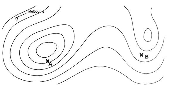
Question 203-9 : On which bearings errors caused by the shorelinecoastal effect reach their maximum ?
Bearings 000° 030° degrees to the coastline.
Coastal refraction or shoreline effect low frequency radio waves will refract or bend near a shoreline especially if they are close to parallel to itleast when bearings normal to coastline radio waves passing the coastline at small angles suffer refraction due to different conducting and reflecting properties over land and sea a false bearing indication is obtained at aircraft flying over sea and taking bearings from ndb located over land the effect is less for an ndb on coast than one inland and on a bearing 90° to coastline then at an oblique angle hence given the choice use beacon at coast and rely on bearings perpendicular to the coastline 2554Bearings 030°-060° degrees to the coastline. bearings perpendicular to the coastline. any bearings in hf band.
Question 203-10 : The doppler effect onto the radio signals is ?
The shift of frequency of the wave due to the relative movement between the transmitter and the receiver.
Increasing or decreasing of the emitting aircraft ground speed. the interference between the direct wave and that reflected by the ground. the fluctuation of their propagation velocity.
Question 203-11 : The d layer and e layer of the atmosphere are part of the ?
Ionosphere.
2551the ionosphere is the ionized component of the earth's upper atmosphere from 60 to 400 km above the surface which is vertically structured in three regions or layers d e and f Troposphere. tropopause. stratosphere.
Question 203-12 : When raising the frequency of an electromagnetic wave the ?
Wavelength decreases.
The relationship between wavelength and frequency is wavelength = speed of light frequencyif frequency increases wavelength decreasesWavelength and amplitude increases. wavelength remains the same. wavelength increases.
Question 203-13 : The phenomenon when a wave bends when it passes around an impenetrable obstacle is ?
Diffraction.
Diffraction is the phenomenon by which wave energy bends around an objectAttenuation. refraction. propagation.
Question 203-14 : The phenomenon of a change in direction of an radio wave em wave occurring due to a change in its speed is called ?
Refraction.
Refraction is the process by which a signal's propagation path bends and the signal changes its speed as it moves from one medium to another different density of the mediums generally the rf energy travels in straight line = following great circle paths however in some cases when there is a change in certain factors the signal's path may change direction the actual extent of the signal's path change varies significantly with the change of the environmentthere are 3 main types of refraction a coastal = the path of rf signal may change as it crosses a coastlineb atmospheric especially low altitude = changes in the path of rf signal may be caused by the changes in temperature pressure or humidityc ionospheric = paths of rf signals may change as they pass through ionized layersAbsorption. diffraction. attenuation.
Question 203-15 : A reason that gps satellites use helical antennae is ?
That the signal has a circular polarization.
Helix antennas also commonly called helical antennas have a very distinctive shape as can be seen in the following picture 2555a helical antenna is an antenna consisting of a conducting wire wound in the form of a helix in most cases helical antennas are mounted over a ground planeThat the signal has a linear polarization. the reduced size of the antennae. the reduced weight of the antennae.
Question 203-16 : The mix of an electromagnetic wave with another is called ?
Interference.
Interference is a phenomenon in which two waves superimpose to form a resultant wave of greater or lower amplitude interference usually refers to the interaction of waves that are correlated or coherent with each other either because they come from the same source or because they have the same or nearly the same frequencythis question exists also with this statement superposition of two em waves of the same or nearly the same frequency is called interference Reflection. diffraction. refraction.
Question 203-17 : Speed of a radio wave ?
300 000 kms.
300 000 m/s. 300 000 km/h. 300 000 m/h
Question 203-18 : For long range ndb's the most common type is ?
Lf non a1a.
Non a2a bfo off for a2a idents 15 w power 10 25nm rangenon a1a bfo on for a1a idents lf non a1a is used for long rangeMf, non a1a. mf, non a2a. lf, non a2a.
Question 203-19 : Mountain effect occurring for instance with ndbs is caused by what physical phenomenon ?
Reflection.
Mountain effect mountain areas can cause reflections and to a lesser extent diffractions and lead to the error direction reading by adfthis effect similar to night effect is obtained in mountainous areas where the energy received from an ndb consists of two or more waves one of them direct and others by reflection from the mountains bearing indications are found to change rapidly until the affected area is passedfor information night effect radio waves take two paths to the radio compass receiver the first and normal path is along the earth's surface if only these waves were received the compass would point directly to the ndb the second path is via one or more wave refracting layers above the earth the ionosphere returning to earth to mix with direct waves complete changes in the nature of the waves take place on this path and produce errors in directionDiffraction. absorption. refraction.
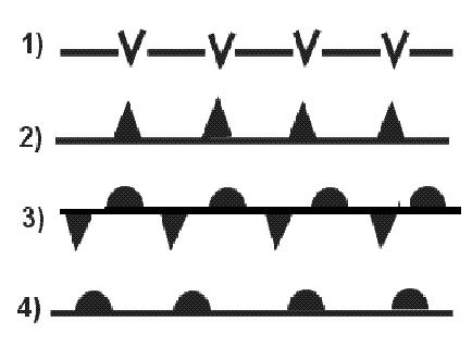
Question 203-20 : Which physical effects affecting wave propagation as shown in the figure 2556 ?
A = refraction b = absorption c = reflection.
A = diffraction b = reflection c = reflection a = absorption b = absorption c = diffraction a = refraction b = attenuation c = interference
Question 203-21 : Which letter in the figure below indicates the 'skip zone' 2557 ?
C.
Read carefully skip zone not 'distance' skip zone dead space is the distance between the limit of the surface wave and the sky waveD. a. b.
Question 203-22 : Which letter in the figure below indicates the 'skip distance' 2557 ?
D.
Read carefully skip distance not 'zone' skip distance is the distance between the transmitter and the point on the surface of the earth where the first sky return arrivesit is the range from the transmitter to the first sky waveC. a. b.
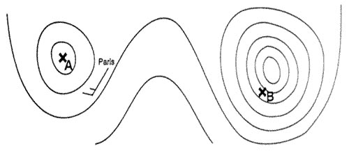
Question 203-23 : You are flying over sea parallel to the coastline an ndb is situated 10 nm inland in which sectors in the diagram does the shorelinecoastal effect reach its minimum 2558 ?
Sectors a + b.
Coastal refraction or shoreline effect low frequency radio waves will refract or bend near a shoreline especially if they are close to parallel to itleast when bearings normal perpendicular to coastlineradio waves passing the coastline at small angles suffer refraction due to different conducting and reflecting properties over land and sea a false bearing indication is obtained at aircraft flying over sea and taking bearings from ndb located over land the effect is less for an ndb on coast than one inland and on a bearing 90° to coastline then at an oblique angle hence given the choice use beacon at coast and rely on bearings perpendicular to the coastlineSectors a + d sectors c + d sectors b + d
Question 203-24 : You are flying parallel to the coastline an ndb is positioned about 10 nm inland in which areas will you observe the shorelinecoastal effect 2558 ?
Area c + d deflection to the coastline.
Coastal refraction or shoreline effect low frequency radio waves will refract or bend near a shoreline especially if they are close to parallel to itleast when bearings normal perpendicular to coastlineradio waves passing the coastline at small angles suffer refraction due to different conducting and reflecting properties over land and sea a false bearing indication is obtained at aircraft flying over sea and taking bearings from ndb located over land the effect is less for an ndb on coast than one inland and on a bearing 90° to coastline then at an oblique angle hence given the choice use beacon at coast and rely on bearings perpendicular to the coastlineArea a + b, deflection to the coastline. area a + d, deflection to the coastline. area b + d, deflection to the coastline.
Question 203-25 : The phenomenon of a change in direction of an em wave occurring at an interface between two different media so that the wave returns into the medium from which it originated is called ?
Reflection.
Ecqb03 august 2016Diffraction. absorption. refraction.
Question 203-26 : What is required to enable an antenna to transmit an electromagnetic wave ?
The antenna has to be fed with an alternating current of high frequency.
Ecqb03 august 2016The antenna mast must be normal to the ground. the antenna has to be fed with a direct current of high frequency. the antenna has to be fed with a direct current of low frequency.
Question 203-27 : An electromagnetic wave has two types of energy field ?
An e electrical field and h magnetic field.
An electromagnetic wave consists of an oscillating electric field e and an oscillating magnetic field h which propagates at the speed of light 2552the e and h fields are perpendicular to each otherAn h electrical field and an e magnetic field. a z electrical field and an h magnetic field. a z magnetic field and an e electrical field.
Question 203-28 : In aviation electronic systems the so called doppler principle may be used in ?
Vor gps and mts and the turbulence mode of awr.
Mts multi spectral targeting systemVor, dme and ils. vor, mti and the mapping mode of awr. vor, dme and gps.
Question 203-29 : The wavelength of a radio signal transmitted at the frequency of 3 ghz is ?
10 cm.
Wavelength in meter = 300 frequency in mhzwavelength in meter = 300 000 frequency in ghzwavelength = 300 000 3 000 000 = 01 m1 m. 1 cm. 100 cm.
Question 203-30 : The phase angle of a wave is ?
The fraction of one wavelength expressed in degrees from 000° to 360°.
The position of a modulation on a wavelength expressed in degrees from 000° to 360°. the angle of the modulation on a wavelength expressed in degrees from 000° to 360°. the deflection on a wave expressed in degrees from 000° to 360°.
Question 203-31 : Wavelength is defined as the ?
Physical distance travelled by a radio wave during one cycle of transmission.
2549Maximum variation of an oscillation. distance traveled by a radio wave in one second. number of oscillations per second.
Question 203-32 : Antennathe ils glide path antenna must be located ?
At approximately 300 m after the threshold and approximately 120 m laterally from the runway centreline.
As close as possible from the runway threshold. at 150 m after the threshold and about 300 m left from the runway centreline. with the localizer antenna, 300 m after the threshold, in the axis.
Question 203-33 : The maximum separation distance between a vor and a dme having the same identifier is ?
2000 ft 600 m .
600 ft (180 m). 60 ft (18 m). 200 ft (60 m).
Question 203-34 : The ground wave surface wave propagates as follows ?
It travels along the earth' surface and follows the curvature of the earth.
It is reflected by the ionosphere towards the ground. it travels under the ground. it is transmitted to the surface of the earth and will be reflected.
Question 203-35 : The sky wave propagates as follows ?
A wave transmitted into space will be reflected back to the earth's surface by the ionosphere.
Ecqb04 november 2017It travels under the ground. it travels along the earth's surface and follows the curvature of the earth. a wave transmitted through the air directly from the transmitter to the receiver.
Question 203-36 : An electromagnetic waves travelling through the air directly from the transmitter to the receiver is a ?
Space wave.
Ecqb04 november 2017Sky wave. ground wave. air wave.
Question 203-37 : Radio waves in the vhf and higher frequency bands propagate mainly as ?
Space waves.
Ecqb04 november 2017Sky waves. ground waves. refracted waves.
Question 203-38 : From which physical phenomenon do sky waves originate ?
Refraction.
Diffraction. absorption. reflection.
Question 203-39 : The skip zone is defined as ?
The area where neither the ground waves nor the sky waves are received.
Ecqb04 november 2017The distance between the transmitter and the point on the surface of the earth where the first sky return arrives. the area covered by the sky waves. the area covered by the space waves.
Question 203-40 : The amplitude of an electromagnetic wave is defined as the ?
Maximum deflection in an oscillation or wave.
2549amplitude maximum deflection in an oscillationPhysical length of an oscillation. number of cycles occurring in one second in a radio wave expressed in hertz (hz). wavelength.
Exclusive rights reserved. Reproduction prohibited under penalty of prosecution.