A free Premium account on the FCL.055 website! Read here
Sign up to unlock all our services and 15164 corrected and explained questions.
Question 204-1 : The definition of frequency modulation is ? [ Exam pilot ]
The information is carried by a modification of the frequency of the carrier
Question 204-2 : Frequency modulation consists of ?
A lf wave on an hf carrier wave.
Frequency modulation the information that is impressed onto the carrier wave by altering the frequency of the carrier 2560A hf wave on an lf carrier wave. an agreement between receiver and transmitter. a system for interference elimination.
Question 204-3 : Modulation is ?
The addition of information onto a radio wave during transmission.
Modulation is addition of information onto a radio wave during transmissionthe goal is to modify the radio frequency signal in order to superimpose audio andor data signal a low frequency signal will be modulated by changing one ore more of its parameters amplitude frequency phase and then added onto a carrier wave which consists of a high frequency this process is known as 'modulation' and is necessary for transporting information via cable or through the airThe amplification of the received radio wave in the detector. the separation of information from the radio wave during receiving. the transformation of the radio wave into a digital signal.
Question 204-4 : Skip distances are increased at night as ?
D layer disappears at night and the e and f layers are used instead.
Ecqb04 november 2017skip distance is the distance between the transmitter and the point on the surface of the earth where the first sky return arrives 2551skip distance will increase for a higher position of the reflecting ionospheric layer at night d layer disappears e layers almost disappears and therefore refraction occurs at a higher level the skip distance is increasedD-layer descends at a lower level, reflection occurs earlier. f-layers disappears at night and the e-layers is used instead. the ionosphere becomes more ionized at night, reflection will be stronger.
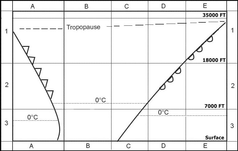
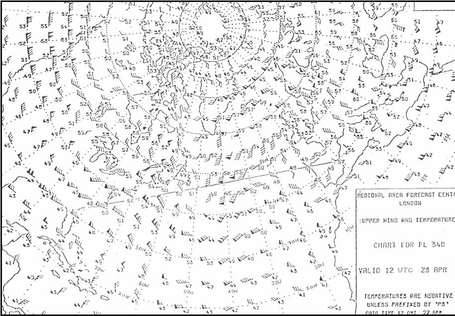
Question 204-5 : Which letter in the figure below indicates the 'ground wave' 2561 ?
A.
B. d. c.
Question 204-6 : A skip zone can be fin at letter s 2561 ?
B and d.
A. c and d. d.
Question 204-7 : The vhf omnirange vor uses the following wavelengths ?
Metric.
Vor beacons operate at shorter ranges and are free from most of the errors that afflict ndbsthey use line of sight frequencies in the vhf band wavelenght from 10 m to 1 m refer f between 108 mhz and 117975 mhz it means from 10m to 1 mwave lenght in m = propagation speed c in mss ÷ frequency f in hz wave lenght in m = 300 000 000 ÷ frequency between 108 000 000 and 117 975 000 hz result will be around 3 metres between 108 mhz and 112 mhz the band is shared with ils so vor frequencies are only allocated at even 100 khz spacingfrom 112 mhz to 117975 mhz the band belongs to vor alone and spacing is reduced to 50 khzthus 1082 mhz and 11335 mhz would be vor frequencies and 1081 mhz would notwithin the vor ils shared frequency range the allocated frequencies are as follows vor = even 100 khz numerals10800 10805 10820 10825 to 11180 11185ils = odd 100 khz numerals10810 10815 10830 10835 t0 11190 11195Decimetric. hectometric. centimetric.
Question 204-8 : Single side band ssb is used ?
In hf two way communication.
Learning objective 06201010303 state that hf meteorological information for aircraft in flight volmet and hf two way communication use a single sidebandwhen we want to send information via radio waves we have to modulate the carrier wave somehow this is the process of adding information to it there are a few ways to do thisin the early days of radio it was done by sending pulse of the carrier wave as morse code pulse modulation these days we can modulate the amplitude of the carrier wave to carry our information or we can modulate the frequency slightly to carry information alsoamplitude modulation is easier to do and far easier to represent visually the peaks and troughs of our carrier wave are modified to create our information wave over the top of each peak and the same information wave under each trough the wave over the peaks is one side band and the wave under the troughs is the other side band two side bands are created but when we send hf radio signals we remove one side band to reduce the required power of the transmitter and the required bandwidth this means that for our uses hf transmissions are single side band ssb With transmissions of the meteorological aerodrome report (metar). in vhf transmissions to reduce transmission power. in hf one-way communication.
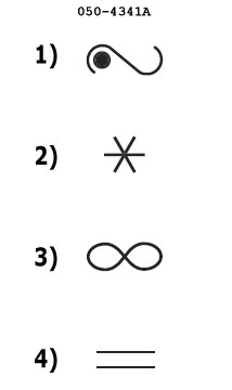
Question 204-9 : What is meant by keying in a1a modulation ?
Interrupting the carrier wave to break it into dots and dashes.
Radio signals have only one carrier wave the carrier wave is used to carry the informationa1a is an abbreviation for the following a = double side band1 = a single channel containing quantized or digital information without the use of a modulating sub carriera = telegraphy for aural receptiona1a is the part of the emission of an interrupted unmodulated carrier wave which requires the beat frequency oscillator bfo to be on for aural reception keying is adding readable data to a carrier wave this readable data is usually formed in morse codeInterrupting the modulating signal to break it into dots and dashes. changing the amplitude of the carrier wave to add information. adding information on the carrier wave by use of a modulating signal.
Question 204-10 : Which of the following summaries lists only directional antennas ?
Refet to figures a directional antenna or beam antenna is an antenna which radiates or receives greater power in specific directions allowing increased performance and reduced interference from unwanted sources in other words directional antennas send and receive signals in one direction only usually in a tightly focused very narrow beamdirectional antennas come in a variety of shapes sizes and designs that fluctuate widely according to their intended purposecommon designs include slotted planar array antennasloop antennasparabolic or 'dish' antennashelical antennas can be directional or omnidirectional note in some authorities the helical antenna is also shown in the correct option as a directional antenna these authorities spain greece Dipole antenna, loop antenna, parabolic antenna, slotted planar array antenna. dipole antenna, sense antenna, parabolic antenna, helical antenna. sense antenna, parabolic antenna, slotted planar array antenna, helical antenna.
Question 204-11 : In aviation electronic systems the so called doppler principle may be used in ?
Vor gps and mti and the turbulence mode of awr.
The doppler effect is where waves electromagnetic in all these cases have a slightly higher detected frequency when the transmitter and receiver are coming together but a lower frequency when moving apart it is a measurable difference as we often know the precise frequency that we should be picking up and so small variations from that can tell us if a transmitter or a reflector is moving towards or away from us and at what speedvors use this principle in doppler vors dvors which are the modern versions of vor beacons the variphase signal of the vor is transmitted by a ring of antennas in a circle and the signal transfers to each consecutive antenna so the transmission point of the signal effectively moves round in a circle this allows an aircraft to receive a frequency modulated signal due to the doppler effect to compare phase difference with the amplitude modulated reference signal and calculate the aircraft's radial gnss including gps systems use the doppler effect to measure an object's speed as the pseudo random noise prn signals are on an exact frequency and the receiver knows the velocities of each satellite so is able to work out the relative movement of the receiver with very small doppler changes in frequencymti moving target indication is less common to hear about but this system allows a radar to know which objects are moving towards or away from the station due to the doppler effect of their reflected pulses it can be used to only show moving targets and remove radar clutterairborne weather radars awrs use the doppler effect to judge the relative movements of moisture particles raindrops hail etc based on the frequency of the reflected returns if this movement is large and erratic the radar system can then show it as an area of turbulence which is useful information for the pilotdmes use a system of time measurement to measure distance from a ground station and the groundspeed function uses the rate of change of that distance not the doppler effectilss use difference in depth of modulation as a method of working out how far off localiserglideslope the aircraft is not the doppler effectawrs have a mapping mode but this does not use any doppler measurements as the ground is supposed to stay stillVor , dme and gps. vor, dme and ils. vor, mti and the mapping mode of awr.
Question 204-12 : A radio signal may be classified by three symbols in accordance with the itu radio regulation eg a1a which statement is true ?
The first symbol indicates the type of modulation of the main carrier.
Itu is known as low speed data typically divided into 3 segments the first segment a letter is the type of modulation the second symbol a number is the type of modulating signal the third segment a letter is the type of information that is being transmitted a1a is an abbreviation for the following a = double sideband amplitude modulation this indicates the bandwidth of the signal 1 = a single channel containing quantized or digital information without the use of a modulating subcarrier a = telegraphy for aural receptionThe three symbols together indicate which device is transmitting on the carrier the second symbol indicates the nature of information to be transmitted the third symbol indicates the nature of the signal modulating the main carrier
Question 204-13 : Vhf very high frequency waves occur in which frequency range ?
The area where neither the ground waves nor the sky waves are received.
Refer to figurea skip zone is a region where a radio transmission can not be received radio waves which travel near to the ground groundwave and towards the ionosphere skywaves have a skip zone the skip zone is a region between the farthest point at which the groundwave can be received and the nearest point at which the refracted skywaves can be receivedthe skip zone is a natural phenomenon that can never be influenced by technical means it can only be reduced by decreasing the frequency of the radio waves reducing the frequency can be done by increasing the ionospheric widthThe area, where only the ground wave is receivable. the area, where ground and sky waves are receivable. the area, where only the sky wave is receivable.
Question 204-15 : Which failure in radio navigation is connected with 'fading' ?
Twilightnight effect.
Adf accuracy and errorsicao requirement is an accuracy of ±6° with a signal to noise ratio no less than 3 1the adf is subject to a number of potential errors staticall forms of static can affect accuracy of the adf in snow and freezing rain precipitation static reduces the accuracy and attenuation reduces the range of bearing informationthunderstormsthunderstorms in the vicinity act as radio beacons and can cause the needle to deviate in their directionin conditions like this and where heavy static is present vhf aids should be used in preference to adfnight effectthe principal propagation method of ndbs is the ground wavehowever it is possible for weak sky waves to be returned at night when the ionosphere is less dense and attenuation is leastreturning sky waves take a longer propagation path than ground waves so they are often out of phasenight effect can be detected by listening for fading on the carrier wave bfo on and by the instrument hunting it is most likely at dawn or duskstation interferencethe long ground waves of lf and mf signals mean that occasionally signals from stations on similar frequencies overlapthis will not cause errors in the daytime if the stations are only used within the protected rangeat night returning sky waves can cause rogue signals at considerable range producing the same problems as night effect coastal refractionspeed of a surface wave is affected by the surface over which it travels faster over water than land this change of speed means the wave is refracted at low altitude as it passes over a coastlinerefraction is always towards the coastan aircraft receiving a refracted wave would give a false indication of the beacon's positionit will place the aircraft nearer to the coast than it actually is this effect is worse the further back from the coast the beacon is sitedquadrantal errorthe wave front from the ndb can be distorted by the aircraft's structure as it approaches the aerialthe error is called quadrantal error because the effect is worst for signals arriving from 45° and 135° left and right of the nose the four quadrants quadrantal error is small and predictableit can be compensated during the installation of the receiver aerial and any residual errors can be shown on a quadrantal error card kept near the instrumentmodern receivers completely remove itdipdip occurs when the receiver sense aerial is masked by the loop aerialdip gives large bearing errors only occurs in a turn and is at its greatest when the ndb is on a relative bearing of 45° and 135° left and right of the nose mountain effectat low altitude multipath signals reflected from terrain can cause erroneous readingsithis effect diminishes with height as hills are further from the line of sight and interfere less with the surface waveStatic discharge mountain effect shoreline/coastal effect
Question 204-16 : The frequency of an airborne weather radar is 933 ghz what is the corresponding wavelength ?
32 cm.
Refer to figureuse the simplified standard formulae in meters = c 300 f inmhz first convert 933 ghz to mhz as seen in the figure 1 ghz is the same as 1000 mhz933 ghz is equal to 9333 mhzfilling in the formulae results in the following = 300 9333 mhz = 0032 m = 32 cm32 m 3.2 m 32 cm
Question 204-17 : What is the frequency of a radio wave with a wavelength of 825 m ?
364 mhz.
Wave lenght in m = propagation speed c in mss ÷ frequency f in hz propagation speed c is a costant 300 000 000 ms or 162 000 nms825 = 300 000 000 ÷ xx = 300 000 000 ÷ 825 = 36363636 hzin our case we must convert 36363636 hz in mhz = ± 364 mhz24.8 khz 36.4 khz 2.48 mhz
Question 204-18 : What is the simplest type of an antenna called ?
Dipole.
Refer to figuresdipole antenna this antenna is the most widely used type of antenna it is the simplest form of an antenna a basic dipole antenna as seen in figure 1 consists of 2 conductors arranged symmetrically with one side of the balanced feedline from the transmitter or receiver attached to eachmonopole antenna this antenna has a more complicated design a monopole antenna as seen in figure 2 consists of a single conductor usually attached to the ground because of the use of only one conductor the monopole antenna has twice the gain of a similar dipole antennaloop antenna loop antenna as the name suggests suggest of a loop of wire loop antennas as seen in figure 3 correspond directly with the magnetic field of the radio wave which means they are insensitive to electrical noisequadrupole antenna as the name suggests this antenna consists of 4 parts this is the most complex form of antenna and therefore not much used as seen in figure 4 it consists of 4 monopole antennas attached in orderMonopole loop antenna quadrupole
Question 204-19 : What type of antenna is used in a modern airborne weather radar ?
Slotted planar antenna.
Airborne weather radar is a type of radar used to provide an indication to pilots of the intensity of convective weathermodern weather radars are mostly doppler radars capable of detecting the motion of rain droplets in addition to intensity of the precipitationairborne weather radar is typically xband pulse modulated and operating in the 8 12 ghz range with a wavelenght approx 3 cm remember well 3 ghz 300ghz correspond ro a wavelenght of 10cm 1mm the shape of the radar beam is very important in the design of a radarfor purposes of airborne weather radar a narrow beam is the most desirable because it concentrates more energy on the target which means more energy will come back in the echoflat plate antennas are better than dish antennas and larger antennas are better than smaller antennas for concentrating the beamthe pulse repetition frequency prf of a radar will determine its maximum rangethe prf must be long enough to allow the echo pulses to return from the maximum range targetthe longer the required range the lower the prf scanning speed comes into play with the prf since a high scanning speed and low prf would cause targets to be missedat least one pulse should be transmitted per a beam width of scanpulse width will determine the minimum range of the radar and also the resolution size of the targetif a target is close and the echo is reflected back to the radar while the transmitter pulse is still being transmitted then obviously that target will be missedmost radars i have worked with had a pulse width of less than 4 microseconds so this isn't a problemalso many radars will shorten their pulse width in map mode allowing a higher degree of resolution for ground targets such as shorelines or islandsDipole omnidirectional antenna loop antenna
Question 204-20 : What happens to the amplitude and frequency of the carrier in a1a keying the amplitude ?
And the frequency both remain constant.
A1a keying is known as low speed data and the carrier wave is simply switched on and off think of it like morse code as a consequence nothing changes in terms of the frequency or amplitude of the waveRemains constant but the frequency increases. increases but the frequency remains constant. and the frequency both increase.
Question 204-21 : Which aeronautical radio frequency band uses refraction within ionospheric layers ?
Hf.
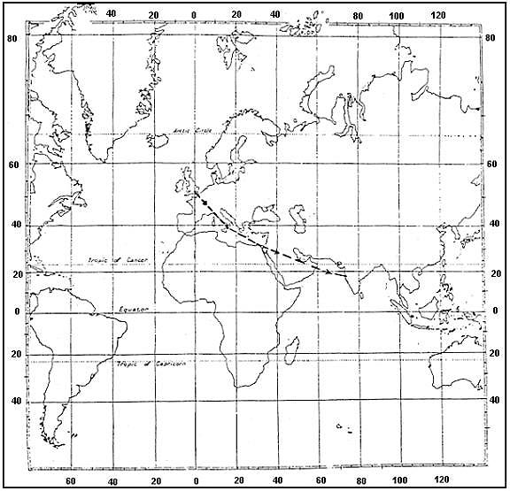
Refer to figurelong distance communication works on skywave propagation where radio waves are directed at an angle to the sky so they refract back to earth from the ionosphere by this method it is given that frequencies in the high frequency hf band can travel beyond the horizon following the curvature of the earth and can be received at long distancesbecause of the refraction and reflection properties of the hf band these frequencies are also good for transmission in mountainous terrains which prevent line of sight communicationsVhf uhf vlf
Question 204-22 : The skip distance of hf transmission will increase with ?
Higher frequency and higher level of the refracting ionospheric layer.
Refer to figureradio waves can propagate in many different ways the most common is as a space wave this is what most people think of when it comes to radio transmission as this is line of sight meaning that the radio waves travel in straight lines onlyanother propagation path is via ground waves which cling to the surface and follow the contours of the earththe third method of propagation is via sky waves which are space waves that interact with the charged particles in the ionosphere when these waves reach the ionosphere the subsequent ionospheric attenuation refracts the waves changing their course until the waves are heading downwards again this is often referred to as reflection by easa so do not be confused it is refraction that occurs it just looks like the reflection from afar and they use the terms almost interchangeablythe skip distance is the distance away from the transmitter where the first sky wave returns to the surface after bouncing off the ionosphere this can create a dead zone of reception for some frequencies which travel as both ground and sky waves as for example the ground waves might stop at 100 nm but the sky waves only begin at 200 nm these numbers are not even close to correct higher frequencies receive less ionospheric attenuation therefore refracting less and not bending as sharply in the ionosphere this means that higher frequency radio signals do not bounce off the ionosphere at steep angles thus making the skip distance longer see the second annex abovethe height of the ionosphere also makes a difference a higher ionosphere means that the signals will travel further before reaching the level where refraction begins and will travel further on the way back down also this means that a higher ionosphere contributes to a longer skip distanceLower frequency and higher level of the refracting ionospheric layer. higher frequency and lower level of the refracting ionospheric layer. lower frequency and lower level of the refracting ionospheric layer.
Question 204-23 : The advantage of slotted antennas in modern radar technology is to… ?
Greatly reduce lateral lobes consequently concentrating more energy into the main beam.
Refer to figures learning objective 06201020301 name the common different types of directional antennas loop antenna used in old automatic direction finding adf receivers parabolic antenna used in weather radars slotted planar array used in more modern weather radarsradars such as awrs airborne weather radars have to be able to send pulses of electromagnetic radiation in one direction all at once this is more difficult than it sounds due to the way that these waves are producedparabolic antennathe older method of directing this energy was by using a parabolic reflector dish which is a shape that reflects all radiation from the focal point in the middle outwards in the same direction and vice versa any radiation from that direction is reflected onto the focal point in the middle this allows for a transmitterreceiver device to be placed in the focal point facing backwards towards the dish and for its transmissions to go forwards ahead of the aircraft and receive the reflected pulses indicating the presence of weatherone of the biggest problems with the parabolic antenna is the side lobes the formation of this main beam of radiation does cause some unwanted extra radiation called side lobes which send some of the energy in a different direction than intended and can cause some spurious and incorrect responses on the radar screenslotted planar array flat plate antenna phased arraythese types of radars use a more efficient modern technique by having a flat plate with numerous waveguide size slots cut into it it can produce a similar beam to the parabolic antenna with much smaller sidelobes the lesser side lobes means that there are less spurious returns and that there is less wasted energy meaning that less energy is needed for the same radar scanthe main beam main lobe of a slotted planar array can also be made thinner than the parabolic antenna beam which would use even less energy allowing for increased range or just lower energy consumptionProduce a wide beam for better target detection. eliminate the need for azimuth slaving. simultaneously transmit weather and mapping beams.
Question 204-24 : Modulation is ?
The process of impressing and transporting information by radio waves.
In electronics and telecommunications modulation is the process of varying one or more properties of a periodic waveform called the carrier signal with a modulating signal that typically contains information to be transmittedmost radio systems in the 20th century used frequency modulation fm or amplitude modulation am for radio broadcastwhy do we need modulation practically speaking modulation is required for high range transmission quality of transmission to avoid the overlapping of signals difference between am and fmamplitude modulation and frequency modulation are used to transmit data using the method of modifying a carrier signalthe am technique is totally different from frequency modulation and phase modulation where the frequency of the carrier signal is varied in the first case and in the second one the phase is varied respectivelyrefer to annex 1amplitude modulationamplitude modulation is a modulation technique where the amplitude of a carrier varies depending on the information signalam radio broadcast signals use lower carrier frequencies this helps them to travel long distancessometimes am signals can be able to bounce off the ionospherethe distance travelled by the am is much larger than the fm annex2 refer to annex 2frequency modulationin this module the frequency of the carrier wave is modified according to the signal that carries informationthe radio signals have large bandwidth than am radio signals which helps to offer much better sound qualityfrequency modulation also enables to transmit stereo signals summary amplitude modulation am frequency modulation fm the radio wave is called a carrier wave and the frequency and phase remain the same the radio wave is called a carrier wave but the amplitude and phase remain the same has poor sound quality but can transmit longer distance has higher bandwidth with better sound quality the frequency range of am radio varies from 535 to 1705 khz the frequency range of fm is 88 to 108 mhz in the higher spectrum more susceptible to noise less susceptible to noiseA continuous wave which is capable of carrying audible signals without modification. to allow the signal to be amplified to the required power level. the process to provide a radio carrier wave for transmission.
Question 204-25 : The unit for measuring frequency is and measures cycles ?
Hertz per second.
Refer to figurefrequency in physics the number of waves that pass a fixed point in unit time also the number of cycles or vibrations undergone during one unit of time by a body in periodic motion a body in periodic motion is said to have undergone one cycle or one vibration after passing through a series of events or positions and returning to its original stateusually frequency f is measured in the hertz unit hz named in honor of the 19th century german physicist heinrich rudolf hertz the hertz measurement is the number of waves that pass by cycle per second for example an a note on a violin string vibrates at about 440 hz 440 vibrations per second Metres, per minute metres, per second hertz, per minute
Question 204-26 : When raising the frequency of an electromagnetic wave the ?
Wavelength decreases.
Wavelength is the distance of one full cycle of the oscillation longer wavelength waves such as radio waves carry low energy this is why we can listen to the radio without any harmful consequences shorter wavelength waves such as x rays carry higher energy that can be hazardous to our health consequently lead aprons are worn to protect our bodies from harmful radiation when we undergo x rays this wavelength frequently relationship is characterized by c= 1 1 c= where c is the speed of light is wavelength and is frequency shorter wavelength means greater frequency and greater frequency means higher energy wavelengths are important in that they tell one what type of wave one is dealing with see the annexWavelength remains the same wavelength increases wavelength and amplitude increases
Question 204-27 : During a flight at fl210 a pilot does not receive any dme distance indication from a dme station located approximately 220 nm awaythe reason for this is that the ?
Aeroplane is below the minimum altitude for line of sight propagation.
Refer to figuredme measures the straight line distance from the aircraft to the ground station in the order of 200 300 nm depending on the aircraft heightthis is called slant range and is slightly more than the actual horizontal distance because of the difference in elevation between the aircraft and the stationthe most extreme case of slant range error occurs when the aircraft passes directly over the station instead of reading zero the dme shows the altitude of the airplane above the station in nautical miles slant range error also affects groundspeed and time to station displays when you're close to the stationdisplayed dme groundspeed drops below actual groundspeed as you approach the station and then climbs back to normal after you pass itdisplayed dme time to station may not count all the way down to zero as you fly over the stationthe dme range slant range can be calculated using the following formula slant range = 123 h1 + h2 h1 = altitude of the aircraft ft h2 = elevation of the dme station ft in our case fl210 ft correspond at 21000ftslant range = 123 21000 + 0 slant range = 123 x 1449slant range = 1782 nmwith the aircraft at a distance of 220 nm we can say that at fl 210 it is beyond the maximum theoretical range or below the line of sight minimum altitude for this distanceAeroplane is circling around the station. the power of the transmitted signal is too weak to be received by the dme station. altitude is too high.
Question 204-28 : Under what conditions can vhf voice communications often suffer interference from transmissions on the same frequency at a distance considerably greater than line of sight ?
A temperature inversion in the atmosphere can cause super refraction .
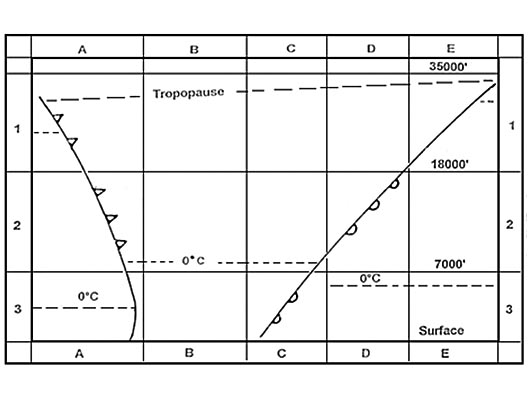
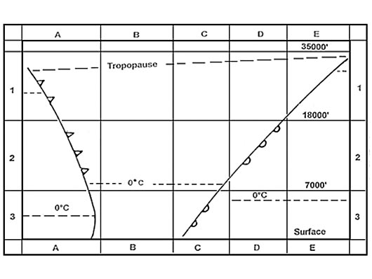
The most important atmospheric effects on radio wave propagation are refraction and reflection refraction can occur in the troposphere or the ionospheretropospheric refraction occurs because the refractive index of the atmosphere decreases as altitude increases leading to a bending of waves back toward the earthconversely ionospheric refraction occurs because of the electrical properties of plasmas that are formed in the ionosphere as a result of ionization of the atmospherereflection off the ionosphere is also possible if the frequency is low enoughwe will differentiate these two effects and refer to the former as atmospheric refraction and the latter as ionospheric propagationthe atmosphere will also attenuate radio signals due to absorption by air molecules water molecules and precipitation rain the most important thing to note is that refractivity is inversely proportional to temperature and directly proportional to pressure and humidityhence as we go higher into the atmosphere the refractivity tends to drop somce the pressure is less and the air is more dry temperature plays a role as well and in reality temperature gradients can cause the refractivity profile to be non monotonicThe interfering signal may be refracted from the ionosphere at night. the interfering signal may be refracted from mountains between the transmitter and receiver. the interfering signal may be refracted as a surface wave over a large expanse of water.
Question 204-29 : Pulse length is expressed as ?
Time.
Pulse lengthpulse length is also known as pulse width or pulse duration as a general definition we can say that pulse length is the nominal duration of a standard pulse which is the time interval between the half amplitude points on the rise and decay points of the curve it is a measurement of how long a pulse isAn amplitude. distance. a frequency.
Question 204-30 : Why do vhf radio signals used for communication and navigation have a limited range ?
Because of the curvature of the earth.
An aircraft uses a range of radio frequencies to navigate to its destination and communicate with air traffic control aircraft short range communication uses vhf band between 118 mhz and 137 mhz to talk with air traffic controlthese vhf frequencies have a line of sight capability meaning that they travel in a straight line whilst the surface of the earth is a downward curved surface declination relative to the signal eventually at a certain distance the receiving aircraft will fall out of the line of sight of the transmitter – because the signals normally do not follow the curvature of the earthGround waves are absorbed by the earth's surface. sky waves are refracted from the d-layer. direct waves interfere with ionosphere waves.
Question 204-31 : According to the international telecommunication union itu code a radio signal may be classified by three symbols the abbreviation a3e is used for the type of transmission in which the carrier wave is ?
Amplitude modulated by a speech signal such as is used for vhf com.
The international telecommunication union itu has designated the type of amplitude modulations designation description a3e am speech communication as used for aeronautical vhf communications double side band full carrier on vhf and uhf the basic amplitude modulation scheme r3e single sideband reduced carrier h3e single sideband full carrier j3e single sideband suppressed carrier on hf b8e independent sideband emission c3f vestigial sidebandA continuous wave interrupted with a keyed morse code ident as used by an ndb. amplitude modulated to transmit the morse code ident, as is used by a vor. interrupted to transmit the morse code identification, as used by an ndb.
Question 204-32 : What does the term antenna shadowing mean ?
The antenna is masked from the transmitter due to the aircraft attitude.
Antenna shadowingshadowing by parts of an aircraft such as a wing may prevent signals from being received if the antenna is not sited properlyto minimize the adverse effects of antenna shading it is important to place antennas on aircraft in such locations where least shading can be expected in any normal flight attitude antennas used for reception of ground based facilities should be on the underside of the aircraft while gps antennas should be on the topThe antenna shielded from the sun in order to reduce the influence of the ionosphere. terrain is in between the receiver and the transmitter. the antenna is placed under a dome.
Question 204-33 : What is the receiver aerial location of a gnss system ?
Top of the fuselage.
Refer to figure antenna shadowingterrain contours or obstacles close to the transmitting or receiving antenna partially block the radio signal resulting in a weaker reception for the same transmission power and distance regardless of the type of wave propagationto minimize the adverse effects of antenna shading it is important to place antennas on aircraft in such locations where least shading can be expected in any normal flight attitude antennas used for reception of ground based facilities should be on the underside of the aircraft while gps antennas should be on the topBottom of the fuselage. left wing tip. top of the tail.
Question 204-34 : The following might be caused by antenna shadowing ?
Poor radio reception of a vor ident signal while the aircraft is making an orbit 360° medium level turn .
Antenna shadowingshadowing by parts of an aircraft such as a wing may prevent signals from being received if the antenna is not sited properlyto minimize the adverse effects of antenna shading it is important to place antennas on aircraft in such locations where least shading can be expected in any normal flight attitude antennas used for reception of ground based facilities should be on the underside of the aircraft while gps antennas should be on the topduring 360º medium level turn the effect of the wing shadowing the aircraft antenna should be consideredA weather radar failing to show a distant turbulent cloud due to the signals being blocked by a nearer cloud. an aircraft appearing as two distinct indications on a radar controller's display. blocking of a vor transmission caused by buildings close to the antenna.
Question 204-35 : What is correct regarding antenna shadowing ?
Reduced reception by an antenna when part of the airframe blocks the signal to the antenna.
Antenna shadowingshadowing by parts of an aircraft such as a wing may prevent signals from being received if the antenna is not sited properlyto minimize the adverse effects of antenna shading it is important to place antennas on aircraft in such locations where least shading can be expected in any normal flight attitude antennas used for reception of ground based facilities should be on the underside of the aircraft while gps antennas should be on the topPoor reception of gps signals due to very weak signals compared to the background noise at that frequency. terrain blocking the path between the transmitter and receiver/aircraft antenna. protection of a radar-reception antenna from the strong signals produced by a nearby transmission antenna.
Question 204-36 : The correct position for the gps antenna on an airplane is ?
On the top of the fuselage.
Antenna shadowingterrain contours or obstacles close to the transmitting or receiving antenna as well as aircraft parts partially block the radio signal resulting in a weaker reception for the same transmission power and distance regardless of the type of wave propagationto minimize the adverse effects of antenna shading it is important to place antennas on aircraft in such locations where least shading can be expected in any normal flight attitude antennas used for reception of ground based facilities should be on the underside of the aircraft while gps antennas should be on the topOn the bottom of the fuselage. in the nose of the aircraft. in the tailplane.
Question 204-37 : A student pilot has just learnt that meteorological information for aircraft en route on long haul flights is sent by radio what kind of radio receiver is needed to receive this information ?
Single sideband receiver.
Refer to figure learning objective 06201010303 state that hf meteorological information for aircraft in flight volmet and hf two way communication use a single sidebandwhen we want to send information via radio waves we have to modulate the carrier wave somehow this is the process of adding information to it there are a few ways to do this in the early days of radio it was done by sending pulse of the carrier wave as morse code pulse modulation these days we can modulate the amplitude of the carrier wave to carry our information or we can modulate the frequency slightly to carry information alsoamplitude modulation is easier to do and far easier to represent visually the peaks and troughs of our carrier wave are modified to create our information wave over the top of each peak and the same information wave under each trough the wave over the peaks is one sideband and the wave under the troughs is the other sideband two sidebands are created but when we send hf radio signals we remove one sideband to reduce the required power of the transmitter and the required bandwidth this means to accept hf radio our receiver has to be of the single sideband ssb typethis question is a bit too ambiguous as it does not mention that we are picking up a hf volmet broadcast in simple terms instead it hints at the hf part as it is a long haul flight currently en route and that it is a volmet as they are trying to pick up meteorological information the learning objective above is very clear on this though and once that lo is known it is obvious what the question writer is getting atVhf receiver. lf/mf receiver. double sideband receiver.
Question 204-38 : Which of the following options contains the correct frequency band propagation path and frequency range for radio communications using a single side band ?
Hf 3 mhz to 30 mhz surface and sky waves.
Refer to figure learning objective 06201010303 state that hf meteorological information for aircraft in flight volmet and hf two way communication use a single sideband learning objective 06201030402 state that radio waves in lf mf and hf propagate as surfaceground waves and sky wavesthis question contains a mixture of two different learning objectives one is to know which frequency range of radio waves use a single side band hf and the second is to know how hf waves propagatewhen we want to send information via radio waves we have to modulate the carrier wave somehow this is the process of adding information to it there are a few ways to do this in the early days of radio it was done by sending pulse of the carrier wave as morse code pulse modulation these days we can modulate the amplitude of the carrier wave to carry our information or we can modulate the frequency slightly to carry information alsoamplitude modulation is easier to do and far easier to represent visually the peaks and troughs of our carrier wave are modified to create our information wave over the top of each peak and the same information wave under each trough the wave over the peaks is one side band and the wave under the troughs is the other side band two side bands are created but when we send hf radio signals we remove one side band to reduce the required power of the transmitter and the required bandwidth this means that hf transmissions are single side band ssb also to note hf radio waves are between 3 30 mhz the range just below familiar vhf and they travel as both surface waves clinging on to the surface of the earth and sky waves bouncing off the ionosphere Vhf, 108 mhz to 117.975 mhz, sky waves. mf, 190 khz to 1750 khz, surface and sky waves. hf, 3 mhz to 30 mhz, surface waves only.
Question 204-39 : International telecommunication union itu classification abbreviations used in aviation include the 1 abbreviation this designates carrier wave emissions amplitude modulated with morse code which is used by 2 ?
1 a2a 2 ndbs.
Learning objective 06201010304 state that the following abbreviations classifications according to international telecommunication union itu regulations are used for aviation applications n0n carrier without modulation as used by non directional radio beacons ndbs a1a carrier with keyed morse code modulation as used by ndbs a2a carrier with amplitude modulated morse code as used by ndbs a3e carrier with amplitude modulated speech used for communication vhf com the itu international telecommunication union produce a classification system for each type of radio wave describing in 3 characters how a radio wave is modulated modulation is the act of putting information onto a radio wave and includes pulse modulation frequency modulation or amplitude modulation the first letter is how the wave is modulated the second character is what type of information is modulated onto the wave digital analogue etc and the third is the information output morse code voice etc the 3 character abbreviation for an old style ndb ident is a1a these have keyed morse code modulation bfo mode must be used to here the ident and a newer ndb ident is a2a which has amplitude modulated morse code so you can listen to it in any mode the ndb carrier wave is n0n it is not modulated and carries no informationthe learning objectives also state that we must know the classification for vhf communication waves which is a3e as per the above lothis is the limit of the learning objectives on these classifications you do not need to find and memorise the table(1) a2a; (2) vors (1) a3e; (2) ndbs (1) a3e; (2) vors
Question 204-40 : 3 30 khz frequency band is referred to ?
Very low frequency vlf.
As seen in the table below the very low frequency vlf band reaches from 3 khz to 30 khz frequency name frequency application very low frequency vlf 3 30 khz nil low frequency lf 30 300 khz ndbadf medium frequency mf 300 3000 khz ndbadf long range communications high frequency hf 3 30 mhz long range communications very high frequency vhf 30 300 mhz short range communication vdf vor ils localizer marker beacons ultra high frequency uhf 300 3000 mhz ils glide path dme ssr satelite communications gnss long range radars super high frequency shf 3 30 ghz radalt awr mls short range radars extremely high frequency ehf 30 300 ghz nil mnemonic to remember the frequency names very very low frequency lovely low frequency maidens medium frequency have high frequency very very high frequency useful ultra high frequency sewing super high frequency equipment extremely high frequencyUltra low frequency, ulf. very high frequency, vhf. low frequency, lf.
Exclusive rights reserved. Reproduction prohibited under penalty of prosecution.