A free Premium account on the FCL.055 website! Read here
Sign up to unlock all our services and 15164 corrected and explained questions.
Question 215-1 : The indication of a 'from to' indicator of a cdi will shift from 'to from' and vice versa when the value difference between the selected course and the measured radial passes in either direction ? [ Preparation civilian ]
090°
Question 215-2 : The bfo selection will ?
Make the carrier wave audible.
Los reference 06202020116 state that on modern aircraft the bfo is activated automaticallybeat frequency oscillator bfo the purpose of a bfo is to allow an unmodulated transmission such as n0na1a to be heard it works by adding a beat frequency to the frequency received from the ndb these two frequencies are inputs to a heterodyne frquency mixing unit the mixing of the two frequencies produces an audible beat frequency which is the difference of the twoon older equipement there is a separate bfo button that can be pressed in order to identify unmodulated ndb signals in modern aircraft the bfo circuit has no push button as the bfo is activated automatically when requiredCause the adf to automatically select the best frequency of nearby ndbs. make the modulation tone audible. increase the transmission signal of the ndb.
Question 215-3 : What leads to the highest interference for an adf ?
Interference during the night.
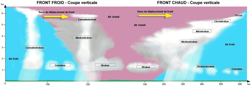
Refer to figurethe night effect has the greatest effect on the accuracy of an adf instrumentnight effectat night the d and e layers weaken and even disappear d more or less disappears due to the lack of radiation from the sun the f layer is the only layer of significant ionization which is present the e and f layers reflect the sky waves at upper lfmf back to the surface making the sky wave reach the receiver out of phase from the ground wave this causes the adf needle to wander between the two signalsif navigation based on ndb at night it is useful to cross check the ndb accuracy with other available radio aidsOther aircraft aerials signal shift during the day interference during the day
Question 215-4 : When considering the workings of a co located vordme station the dme has ?
Same ident different tone.
Although dme operates in a separate frequency band its frequencies are paired with a vor ils or localizer frequency when the pilot of a dme equipped aircraft tunes the frequency of a vor or ils with dme the frequency of the co located dme is automatically tuned the aircraft interrogates the dme ground station with a pulsed signal and the station replies aircraft equipment measures the time between transmission and reception to determine the distance from that groundspeed and time to station can be derivedassociated beacons are beacons with the same ident transmitted at different tones for vors and dmes to be associated they must be less than 100ft 30m apart if used as a terminal aid if used for any other purpose they must be less than 2000ft 600m apart associated tacans and vors are called vortacswhen beacons are associated the three letter morse ident is sent every seven and a half seconds one comes from the dme the next three from the vor the pitch of the dme ident is often higher than the vor ident if beacons fail to meet these criteria they may be given similar idents a dme within 6nm of an en route vor might have the last letter of its ident changed to z eg the vor ident might be lip and the dme lizDifferent ident, different tone different ident, same tone same ident, same tone
Question 215-5 : Which one of the following has a limited range ?
Tvor.
Cvor this was the first generation of vor equipment cvor signals are emitted by a rotating antenna these have a fm reference signaldvor doppler vor is an evolution of cvor providing improved signal quality and accuracy by reducing scalloping error the reference signal of dvor is amplitude modulated and the variable signal is frequency modulated exactly the opposite of cvortvor terminal vors as the name suggests are located in terminal areas of aerodromes these are power limited to 50 w with a range of 25 nm they often form part of departure and arrival structures therefore these are normally positioned along the runway centrelinevot the vot or sometimes abbreviated as vort is a test vor facility sometimesprovided at aerodromesand is not used for navigation pilots on the ground can tune in to this facility and check the receiver accuracy of the aircraftDvor vot cvor
Question 215-6 : What is the main difference between cat iiia and cat iiib ?
Both allows a 'no decision height' dh but require different rvrs.
This information is now outdated in november 2022 easa air ops removed cat iiia iiib and iiic in favor of a simplified system as a result this question should no longer appear in exams however since some caas are slow to update their databases we will keep it as a live question for nowthe operational performance category of an aircraft’s ils equipment depends on its airborne installation these are classified as type a minimum descent height dh at or above 75 m 250 ft type b dh below 75 m 250 ft further categorised as cat i dh not lower than 60 m 200 ft with visibility 800 m or rvr 550 mcat ii dh between 30 m 100 ft and 60 m 200 ft with rvr 300 mcat iiia dh below 30 m 100 ft or no dh with rvr 175 mcat iiib dh below 15 m 50 ft or no dh with rvr between 50 m and 175 mcat iiic no dh and no rvr limitationsOnly cat iiia have no rvr. only cat iiib have rvr. only cat iiib allows a 'no decision height' (dh).
Question 215-7 : An error that reduces the bearing accuracy on the adf when the aeroplane is not wings level is known as ?
Dip error.
Adfthe adf is subjected to a number of potential errors static interference precipitation and thunderstorms station interference night effect mountain effect coastal refraction quadrantal error bank angle dip lack of failure warninghowever the error which reduces adf accuracy during a bankturn is known as bank angle dip error => when an aircraft is in a turn the loop antenna position is compromised the effect is that when in a turn and pointing to or from a station the adf needle will dip by up to 10º towards the low wing causing the adf instrument to be off balance this error is only present when the aircraft is not in level flightMountain effect. quadrantal error. static interference.
Question 215-8 : The reading of the rmi bearing is 300° at the tip of the needle the magnetic variation at the dr position is 22°w the magnetic variation at the ndb is 24°w and the deviation is 2° the compass heading is 020° the true bearing is… ?
276°.
Refer to figurewe are required to determine the true bearing to the ndb typically an rmi shows magnetic heading and bearings however based on the information provided in the question rmi deviation we can infer that the rmi readings will be relative to compass northgiven that the adf is tuned to an ndb the adf needle on the rmi works as follows the tip of the adf needle indicates the compass bearing to the ndb 300° the tail of the adf needle indicates the compass bearing from the ndb 120° in this case we assume that the rmi is subjected to electromagnetic interference and therefore deviation is applied 2ºw westerly deviation compass north is 2° west of magnetic northlet's start by converting compass heading to magnetic heading deviation west compass best deviation east compass leastmagnetic bearing to the ndb = compass bearing to the ndb 002° = 300° 002° = 298°since the question asks for true bearing we need to correct for magnetic variation variation west magnetic best variation east magnetic least remember that for ndbadf bearings the bearings are taken at the aircraft therefore the magnetic variation applicable at the aircraft's position is to be used variation at the dr position = 22° west magnetic north is 22° west of true northtrue bearing to the ndb = magnetic bearing to the ndb 022° = 298° 022° = 276°274° 092° 294°
Question 215-9 : The approximate angular coverage of reliable navigation information for a 3° ils glide path out to a distance of 10 nm is ?
135° above the horizontal to 525° above the horizontal and 8° each side of the localiser centreline.
Refer to figureglidepath coveragethe coverage in the vertical plane of glide slope extends from 045 to 175 where is the nominal glidepath angle above the surface therefore for our 3º glideslope this is 3º x 045 = 135º and 3º x 175 = 525º icao annex 10 3153 coverage31531 the glide path equipment shall provide signals sufficient to allow satisfactory operation of a typical aircraft installation in sectors of 8 degrees in azimuth on each side of the centre line of the ils glide path to a distance of at least 185 km 10 nm up to 175 and down to 045 above the horizontal or to such lower angle down to 030 as required to safeguard the promulgated glide path intercept procedure0.45° above the horizontal to 1.75° above the glide path and 8° each side of the localiser centreline. 3° above and below the glide path and 10° each side of the localiser centreline. 0.7° above and below the glide path and 2.5° each side of the localiser centreline.
Question 215-10 : What is the minimum equipment for mls segmented and curved approaches ?
Dmep.
06202060203 los illustrate that segmented and curved approaches can only be executed with dmep installedthe technological background for segmented and curved approaches is provided by the dme p an mls without a serviceable dme p may provide approach guidance however the curved and segmented approach capabilities are lost as the segments can no longer be defined in 3d nevertheless if the aircraft is flown along the magnetic track of the runway centreline the az and el functions can provide approach guidance in the form of a straight on approach which provides an ils type of approach in terms of flight pathDme dme/dme pairing loc
Question 215-11 : Which of the following statements about the mls is correct ?
It operates on one of 200 channels in the band 503 ghz to 509 ghz shf .
The microwave landing system mls was designed to replace ils with an advanced precision approach system that would overcome the disadvantages of ils and also provide greater flexibility to its users mls is a precision approach and landing system that provides position information and various ground to air data the position information is provided in a wide coverage sector and is determined by an azimuth angle measurement an elevation measurement and a range measurement mls operates in 200 channels available worldwide in the shf band 5031 – 5090 mhz 503 – 509 ghz It operates on one of 126 channels within an allocated frequency spread of 960 to 1215 mhz (uhf). it operates in the vhf band and the frequency allocation is between 108.1 to 111.95 mhz. it operates on one of 40 channels in the band 329.15 to 335 mhz (uhf).
Question 215-12 : The output data given by a basic vordme based area navigation system when tracking inbound to a phantom waypoint enroute mode is ?
Cross track distance and distance to go.
Phantom waypoints are points in space that are created with reference to ground stationsmost vors are dme paired to provide a rho theta service bearing and distance respectively in a paired vordme station the vor provides the angle of the line to determine the position parameter distance is provided by dme that is couple with the vor therefore a vor determines a radial that is a straight line originating from a ground station at a defined angle the dme determines the slant range from the fix providing the distance in nautical miles therefore defining the position of the aircraft the vordme is artificially moved so that its position coincides with the position of the phantom waypoint it then provides cross track distance and distance to go to the inbound radial to the phantom waypointAircraft position in latitude and longitude. true airspeed and drift angle. wind velocity.
Question 215-13 : What is correct regarding the sensitive and critical areas of an ils installation ?
The critical area is an area where vehicles including aircraft are prohibited during all ils operations whereas the sensitive area is an area where movement and parking of vehicles including aircraft is controlled during all ils operations.
Refer to figureicao annex 10attachment ca the ils critical area is an area of defined dimensions about the localizer and glide path antennas where vehicles including aircraft are excluded during all ils operations the critical area is protected because the presence of vehicles andor aircraft inside its boundaries will cause unacceptable disturbance to the ils signal in space b the ils sensitive area is an area extending beyond the critical area where the parking andor movement of vehicles including aircraft is controlled to prevent the possibility of unacceptable interference to the ils signal during ils operations the sensitive area is protected against interference caused by large moving objects outside the critical area but still normally within the airfield boundaryThe critical area is an area where movement and parking of vehicles, including aircraft, is controlled during all ils operations, the sensitive area is a larger area where the same restrictions apply when aircraft are inside 2 nm on the approach. the sensitive area is an area where vehicles, including aircraft, are prohibited during all ils operations whereas the critical area is an area where movement and parking of vehicles, including aircraft, is controlled during all ils operations. the critical area is an area where vehicles, including aircraft, are prohibited during all ils operations, the sensitive area is a larger area where the same restrictions apply when aircraft are inside 2 nm on the approach.
Question 215-14 : What is the function of a marker beacon on an ils approach ?
It indicates aircraft's horizontal position during the approach.
Marker beacons are placed in a predetermined sequence before the threshold the task of the markers is to produce a radiation pattern with a vertical beam upwards by locating the markers at set distances before the threshold the pilot can expect to fly above the markers at known distances consequently the remaining distance from the final approach can be monitored therefore we can say that the marker beacons indicate the aircraft’s horizontal position during the approachIt is used to indicate a requirement to commence the final approach procedure. it is used to indicate a requirement to initiate a configuration change. it is to indicate aircraft's vertical position in relation to the glide path.
Question 215-15 : Determine the distance which will be shown on a dme display when the aircraft is at fl 240 and 4 nm plan range from the dme station for the calculation use the following assumptionsapproximations qnh is 1013 hpa pressure altitude is true altitude result to the nearest whole nautical mile ?
6 nm.
Refer to figurethe question states that we can regard pressure altitude to be the true altitude therefore true altitude equals 24 000 ft 24 000 ft 6 076 = 4 nm approx using the pythagoras theorem x2 = 42 + 42x2 = 32x = 32 = 565 nm3 nm 4 nm 8 nm
Question 215-16 : What does the information displayed to pilots when using a microwave landing system include ?
2d presentation of a 3d segmented approach.
Refer to figure interpretation of microwave landing system mls guidancethe airborne equipment is designed to continuously indicate the relative position of the aircraft and the selected course height and distancethe main feature to understand is the presentation on board is such that the two cross bars showing deviation in azimuth and elevation are computer computed deviation relative to the active programmed segment is presented and not the centre line as it is for the ils the information displayed is a 2d presentation of a 3d segmented approach1d presentation of a 2d straight in approach. 4d presentation of a vertical 3d approach. 3d presentation of a 4d curved approach.
Question 215-17 : The pilot is plotting the aircraft position using a vor and a dme the dme is 500 meters away from the vor the position fix formed will be a straight vor position line crossing a dme position line which itself is a ?
Circle centered on the dme.
Refer to figurefor any type of navigation aid a position line is constructed by the series of points that a given radio navigation aid may define for instance with a vor the position line is a straight line originating from the station in the case of a dme the dme displays a distance information from a fix the position of the aircraft may be anywhere on a circle with the dme in the centre with a radius that is the range from the dmeParabolic arc centered on the dme. parabolic arc centered on the vor. circle centered on the vor.
Question 215-18 : A tuned ils can be identified through a morse code which is ?
Made audible via the audio control panel in nav.
The audible identifier of an ils is normally a 3 letter morse code that represents the 3 letter identifier of the ils it may also be plain text the morse code identifier is transmitted every 10 seconds on the audible channel of the ils by modulating the localiser frequency this does not affect the display of the ils information in the aircraft the morse code may be made audible via the audio control panel in navfor instance on the boeing 737 800 audio control panel there is no separate ils selector nav 1 or 2 will work for both vor or ils whatever is tuned on vhf nav 1 or 2Decoded in text, showing the frequency and runway number. made visible through the three flashing marker lights. shown on the related ils localiser display.
Question 215-19 : Determine the true bearing from the ndb to the aircraft given compass heading 241° adf indication needle head 162° deviation +3° variation 13°e ?
239° t.
Refer to figurethis question is somewhat misleading we believe there is information missing we assume that the examiner forgot to mention that this is a fixed card adf therefore adf indication means relative bearing true bearing from the aircraft to the ndb = true heading + relative bearing 1 determine the magnetic heading +3º stands for an east deviationdeviation east compass least magnetic heading ºm = 241º + 3º = 244º 2 determine the true heading variation east magnetic least true heading ºt = 244º + 13º = 257º 3 determine the true bearing to the beacon true bearing = true heading + relative bearing 257º + 162º = 419º 360º = 059ºto get the true bearing from the beacon we must add 180º 059º + 180º = 239ºt059º(t) 223º(t) 213°(t)
Question 215-20 : What can be obtained on the nav receiver by selecting one vhf frequency in the range of 108 to 112 mhz ?
Rho theta information from a terminal vordme can be obtained.
The band 108 – 112 mhz is used by ils localizer and vor on different channels while the band 112 – 118 mhz is used only by vor within the band 108 – 112 mhz all channels on even multiples of 100 khz 10820 10840 etc are used for vor normally channels spaced 100 khz are used however in congested areas also the intermediate channels 50 khz may be used the vor channels in this sub band are usually used for terminal vor with short range within the 112 – 118 mhz portion of the band all channels 100 and 50 khz are available for vor serviceswith regards to this question it is important to establish the meaning of rho and theta rho represents range distance and theta represents track bearing rho rho could be dmedmetheta theta could represent vorndbrho theta means vordme or ilsdmeRho-theta information from an en-route vor/dme station can be obtained. theta-theta information from en-route vors can be obtained. rho-rho information from an ils/dme can be obtained.
Question 215-21 : What is the difference of cat ii and cat iii ?
Only cat iii allows no dha.
The highest accuracy approaches are the cat iii approaches that may provide guidance all the way to the runway with no requirement for decision height cat iiib nor for runway visual range cat iiic Only cat iii requires a radio altimeter. only cat iii requires no rvr. only cat ii requires no rvr.
Question 215-22 : What is true about ils marker beacons ?
They are used to check the horizontal distance from the runway.
Los reference 06202050103 explain that marker beacons produce radiation patterns to indicate predetermined distances from the threshold along the ils gpmarker beacons are placed in a predetermined sequence before the threshold the task of the markers is to produce a radiation pattern with a vertical beam upwards by locating the markers at set distances before the threshold the pilot can expect to fly above the markers at known distances consequently the remaining distance from the final approach can be monitored therefore we can say that the marker beacons indicate the aircraft’s horizontal position during the approachThey are used to check the altitude at the marker beacon location. they have the same colors but have different morse code identifiers. marker beacons are only used for cat iii approaches.
Question 215-23 : Ils marker beacons send out a morse code for identification purposes where can you retrieve the morse code ?
The audio control panel in nav.
The audible identifier of an ils is normally a 3 letter morse code that represents the 3 letter identifier of the ils it may also be plain text the morse code identifier is transmitted every 10 seconds on the audible channel of the ils by modulating the localiser frequency this does not affect the display of the ils information in the aircraft the morse code may be made audible via the audio control panel in navfor instance on the boeing 737 800 audio control panel there is no separate ils selector nav 1 or 2 will work for both vor or ils whatever is tuned on vhf nav 1 or 2Flashing lights of the marker beacons. the ils display system. the ndb ident close to the runway.
Question 215-24 : An aircraft is on hdg 030 and on a qdm 320 to an ndb turning left towards the ndb the pilot notices the adf needle moving rapidly to the left why ?
Dip.
Los reference 06202020503 explain that the bank angle of the aircraft causes a dip errordip error is an inaccurate reading of the bearing information when the aircraft is in a bank this is because the adf receiver system was designed to work when in horizontal flight when a turn is initiated the indicated bearing is modified the needle will cause an error towards the direction of whichever wing is banked downCoastal refraction. multipath effect. quadrantal error.
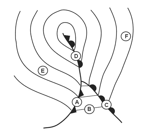
Question 215-25 : A crew is briefing for a procedural vor approach that requires a procedure turn for their destination airport which involves a 80° turn to the left this procedure turn consists of a straight track with track guidance on the 098° radial from a vor followed by a turn of left to a heading of 018° ?
260° turn to the right to intercept the inbound track.
Refer to figureicao doc 8168322 reversal procedureb 80°260° procedure turn see figure i 4 3 1 b starts at a facility or fix and consists of 1 a straight leg with track guidance this straight leg may be timed or may be limited by a radial or dme distance 2 an 80° turn 3 a 260° turn in the opposite direction to intercept the inbound trackthe 80°260° procedure turn is an alternative to the 45°180° procedure turn a above unless specifically excludedTimed straight leg without track guidance and a 180° turn to the right to intercept the inbound track. timed turn to the left to intercept the inbound track. timed straight leg without track guidance and a 180° turn to the left to intercept the inbound track.
Question 215-26 : According to the ils coverage area as defined by icao annex 10 the pilot will be guaranteed a reliable signal from the localizer at… ?
20 nm from the threshold on an inbound course and 8º displaced from the localizer centreline.
Glidepaththe glide path equipment shall provide signals sufficient to allow satisfactory operation of a typical aircraft installation in sectors of 8 degrees in azimuth on each side of the centre line of the ils glide path to a distance of at least 185 km 10 nm up to 175 and down to 045 above the horizontal or to such lower angle down to 030 as required to safeguard the promulgated glide path intercept procedurelocalizerthe localizer coverage sector shall extend from the centre of the localizer antenna system to distances of 463 km 25 nm within plus or minus 10 degrees from the front course line 315 km 17 nm between 10 degrees and 35 degrees from the front course line 185 km 10 nm outside of plus or minus 35 degrees from the front course line if coverage is provided in this case we know localizer coverage up to 25 nm ± 10° and 17 nm ± 35° now to be guaranteed coverage the aircraft should be within these limits therefore 27 nm ± 8° => outside coverage area of 25 nm19 nm ± 13° => outside coverage of 10° from centerline10 nm ± 38° => outside max of 35° from centerline20 nm ± 8° => within 25 nm and ± 10° of centerline10 nm from the threshold on an inbound course and 38° displaced from the localizer centreline. 19 nm from the threshold on an inbound course and 13° displaced from the localizer centreline. 27 nm from the threshold on an inbound course and 8° displaced from the localizer centreline.
Question 215-27 : What does the class letter associated with vdf bearings relate to ?
Level of accuracy.
According to icao annex 10 the vdf information is divided into four classes a b c and d the classes are defined by the range of accuracy defined by degrees based on the following table classes accurate to a range within class a ± 2º class b ± 5º class c ± 10º class d worse than class cAny one of the q-code, depending on the pilot’s request. availability of vdf station. qdm.
Question 215-28 : According to icao doc 8168 the maximum safe deviation below the glide path during ils approach is indicated by a half scale deflection on your instrument the indicated deflection is more than half scale deflection what shall the pilot do ?
Initiate a go around.
Icao doc 8168 555 protection of the precision segment5552 the protection area assumes that the pilot does not normally deviate from the centre line more than half scale deflection after being established on track thereafter the aircraft should adhere to the on course on glide pathelevation angle position since a more than half course sector deflection or a more than half course fly up deflection combined with other allowable system tolerances could place the aircraft in the vicinity of the edge or bottom of the protected airspace where loss of protection from obstacles can occur the maximum allowed safe deviation of the aircraft is half scale deflection in case of a larger deflection the pilot should initiate a go aroundAct at the discretion of the commander in any case. try to get back to the correct glide path. act at his/her discretion (pilot's discretion).
Question 215-29 : An aircraft is flying a magnetic heading of 120º and the rbi shows the ndb at a relative bearing of 270º choose the correct statement ?
The magnetic bearing to the beacon is 030º.
Refer to figure magnetic heading 120º relative bearing of the ndb from the aircraft 270ºmagnetic bearing from the aircraft to the ndb = magnetic heading mh + relative bearing of ndb from the aircraft magnetic bearing from the aircraft to the ndb = 120º + 270º = 030º maintaining a magnetic heading of 120º the magnetic bearing from the beacon is 030º incorrect the magnetic bearing of the aircraft from the ndb will be the reciprocal of 030º 030º + 180º = 210º turning into a magnetic heading of 030º the magnetic bearing to the beacon will be 210º incorrect if we turn into a magnetic heading of 030° the aircraft horizontal axis will coincide with the line that connects the aircraft and the ndb therefore the relative bearing will be 000º360º magnetic bearing from the aircraft to the ndb = magnetic heading mh + relative bearing of ndb from the aircraft magnetic bearing from the aircraft to the ndb = 030º + 000º = 030ºTurning into a magnetic heading of 030º, the magnetic bearing from the beacon will be 030º. the magnetic bearing from the beacon is 030º. turning into a magnetic heading of 030º, the magnetic bearing to the beacon will be 210º.
Question 215-30 : Preparing for the approach the flight crew tune two ndb frequencies which are situated in similar geographical areas ndb1 has a significantly higher power output than ndb2 what is correct regarding the ndb ranges ?
Ndb1 has a greater range.
Several factors affect the range of an ndb transmission the most significant effect is the transmission power output depending on the desired range of operation different types of ndbs have different transmission powers the range obtained is proportional to the square of the power transmitted as a result a range twice as far requires four times the power the ndb range is also limited by frequency lower frequencies result in longer ground wavesAs range depends on frequency, not power, the ndb with the higher frequency has the greater range. ndb2 has the greater range. ndb1 and ndb2 have the same range.
Question 215-31 : Under what circumstances would an adf bearing be affected by dip error ?
The aircraft banking.
Los reference 06202020503 explain that the bank angle of the aircraft causes a dip errordip error is an inaccurate reading of the bearing information when the aircraft is in a bank this is because the adf receiver system was designed to work when in horizontal flight when a turn is initiated the indicated bearing is modified the needle will cause an error towards the direction of whichever wing is banked downThe ndb being on a bearing at 45° to the aircraft’s longitudinal axis. the aircraft banking or accelerating. the aircraft flying at a low level in a mountainous area.
Question 215-32 : Which of the following procedures is used to identify an ndb station ?
In case of a2 modulation use the adf function.
06201010304 state that the following abbreviations classifications according to international telecommunication union itu regulations are used for aviation applications n0n carrier without modulation as used by non directional radio beacons ndbs a1a carrier with keyed morse code modulation as used by ndbs a2a carrier with amplitude modulated morse code as used by ndbs a3e carrier with amplitude modulated speech used for communication vhf com to identify a modulated ndb station the carrier wave is modulated in amplitude a2a with a tone of 400 or 1 020 hz which provides the morse code for identificationto listen to the identification of an unmodulated non a1a ndb the pilot must activate a system known as the beat frequency oscillator bfo by switching it on the bfo remains active as long as the beacon is in use for navigation this allows the pilot to identify the ndb stationlet's analyze each option separately 'in case of a3 modulation use the vhf com function' incorrect the onboard adf equipment does not have a vhf com function additionally a3 modulation is utilized in vhf communications not in ndb navigation'in case of n0n modulation use the bfo function' incorrect while all ndb stations transmit n0n carrier waves the bfo is only necessary when the wave type includes a1a modulation therefore for n0n a2a transmissions which are still a type of n0n wave the bfo is not required'in case of a2 modulation use the adf function' correct the adf function represents the standard operational mode of adf equipment when selected it enables the pilot to hear the identification signals of n0n a2a transmissions'in case of a1 modulation use the ant function' incorrect in most light aircraft equipped with adf equipment the antenna ant function is activated when the adf button is in the out position this function is used to test the adf equipment and improve the audio reception of identifications from ndb stations that transmit n0n a2a signals while the ant function is selected the adf needle will be deactivated and will rotate 90° from its current indicationIn case of a3 modulation, use the vhf-com function. in case of n0n modulation, use the bfo function. in case of a1 modulation, use the ant function.
Question 215-33 : How do you tune mls system in your aircraft select two of the following combination 1 approach can only be upload from fms 2 select the appropriate channel number 3 course obtained from atc only 4 select the appropriate glideslope angle for approach ?
2 and 4.
Refer to figuremls principle of operationmls employs the principle of time division multiplexing tdm see figure 105 whereby only one frequency is used on a channel but the transmissions from the various angle and data ground equipments are synchronised to assure interference free operations on the common radio frequencythe airborne equipment is designed to continuously display the position of the aircraft in relation to the preselected course and glide path along with distance information during approach as well as during departure1 and 2. 2 and 3. 1 and 3.
Question 215-34 : The vdf class letter indicates the accuracy of the bearing information in terms of the ?
Angle in degrees.
According to icao annex 10 the vdf information is divided into four classes a b c and d the classes are defined by the range of accuracy defined by degrees based on the following table classes accurate to a range within class a ± 2º class b ± 5º class c ± 10º class d less than class cWidth in minutes. time in seconds. range in nm.
Question 215-35 : Navigating to an ndb at dusk you notice the adf needle swinging erratically what could be the reason ?
Interference occurs between the ground wave and sky wave causing the signal to fade when the two waves are out of phases.
Refer to figurenight effectnight effect is due to the interference between ground waves and sky waves emitted by the same ndb stationthe principal propagation method of ndbs is the ground wave however it is possible for weak sky waves to be returned at night when the ionosphere is less dense and attenuation is least returning sky waves take a longer propagation path than ground waves so they are often out of phasenight effect can be detected by listening for fading on the carrier wave bfo on and by the instrument hunting it is most likely at dawn or duskSky waves are amplified by the ionosphere, which causes the adf needle to alternate between the sky wave and the ground wave. the ionospheric reflections travel shorter distances than the ground signal, which causes fading of the signal when they interfere. interference between the ground wave and sky wave, which causes fading when the signals arrive at the receiver in phase.
Question 215-36 : It is expected for pilots to apply wind correction angles to the aircraft heading while following the tracks depicted in a procedure as described in pans ops doc 8168 procedures for air navigation services — aircraft operations how is this practice reflected in real world while tracking to or from ?
The head or tail of the needle may point slightly left or right of the top of the instrument when maintaining the appropriate qdm or qdr.
Refer to figure the needle of an adf always points towards the ndb that it is tuned into relative bearings are measured from the aircraft heading to the ndb when tracking towards a ndb the relative bearing equals to 360 degrees minus wind correction angle when tracking away from a ndb the relative bearing equals to 180 degrees minus wind correction angle note the wind correction angle is added to track to give headings it can be seen that the head or tail of the needle need not be pointing straight up when there's wind to correct for hence once the aircraft is established on the depicted track the head or tail of the needle will point straight up on the instrument regardless of wind conditions is not the correct option even if there's no wind the head of the needle will be pointing at 180 degrees relative to the top of the instrument when tracking outbound of ndb thus the head of the needle will be pointing at 3600 when the aircraft is established on the inbound or outbound track is incorrect from the diagram it is clear that relative bearing only equals to the magnitude of the wind correction angle when tracking inbound and the wind correction angle is negative therefore the relative bearing will be equal to the wind correction angle required to maintain the depicted track towards or away from the ndb is incorrect as well the only option left is the head or tail of the needle may point slightly left or right of the top of the instrument when maintaining the appropriate qdm or qdr which is correct when crosswind is light when crosswind is strong the head or tail of the needle may point significantly from the left or right of the instrument though when maintaining the appropriate qdm or qdr however it is the most sensible answer choice present in this questionOnce the aircraft is established on the depicted track the head or tail of the needle will point straight up on the instrument regardless of wind conditions. the head of the needle will be pointing at 3600 when the aircraft is established on the inbound or outbound track. the relative bearing will be equal to the wind correction angle required to maintain the depicted track towards or away from the ndb.
Question 215-37 : You are flying in canada using a vor to navigate you are on the 190° radial the variation at the vor is 2°w and at the aircraft is 2°e the true bearing from the vor to the aircraft is ?
188°.
Refer to figure usually a magnetic heading vor or ndb reading magnetic too is provided which needs converting to a true headingbearing by applying magnetic variation we have 3 cases now aircraft heading apply the variation at the aircraft's position find out the value of the variation from the chart and apply it to your headingndb bearing apply the variation at the aircraft's position because this is where the bearing is obtained from the ndb equipment calculates the bearing information at the equipment onboard so you need to apply the variation at the same locationvor radial apply the variation at the vor's position because this is where the radial is obtained from the vor station whatever the vor is conventional or doppler it identifies the radial where you are on and then send it to you so you have to apply the variation where the station is located atas far as the variation at the vor station is 2w and following the rule of variation west magnetic is best so we have to subtract the variation from the readout radial to get the true bearing in order to plot it on the chart or for any other usage 190° 2° = 188° note in canada airspace northern domestic airspace nda is the area of compass unreliability within which runways and navaids are oriented to true north this question appeared in the exam exactly in this way so the examiner has assumed that we are in the southern domestic airspace of canada008° 192° 012°
Question 215-38 : Icao doc 8168 describes amongst others holding procedures the pilot should start the timing for the outbound leg of the holding pattern when passing abeam the holding fix or wings level whichever is later if the holding fix is ndb the wings are level and the pilot uses an rbi to fly the procedure ?
Approximately 090 degrees or 270 degrees.
The question references an rbi which is a relative bearing indicator also know as a fixed card adf this only shows the direction to an ndb from the direction you are currently facing and is the simplest type of adf displaythe question mentions that you should start the timing for the outbound leg when wings level or abeam the fix whichever is later it then specifies that we are already wings level so we simply have to identify at which point we are abeam the ndbthis would be whenever the rbi shows 90° or 270° as holding patterns can be standard right hand turns or non standard left hand turns which would place you on opposite sides of the fixApproximately 180 degrees or 360 degrees. 90 degrees left or right. 90 degrees left or right of the inbound course.
Question 215-39 : When intercepting a selected radial the flight director indicates the ?
Optimum instantaneous bank angle to reach the selected radial.
The flight directors provide information for the pilot to join a desired path with the optimum attitude flight director information supplied by a fd computer is presented in the form of command bars on the attitude director indicator adi the vertical command bar of the fd supplies information about the direction and magnitude of the corrections to be applied to the bank angle of the aircraft since it is always associated with the roll channel therefore when intercepting a selected radial the fds will indicate the optimum instantaneous bank angle to reach the selected radialBank angle 45. bank angle to reach the selected radial over a minimum distance. bank angle to reach the selected radial in minimum time.
Question 215-40 : An aircraft is being radar vectored downwind for the ils to runway 27 of a regional airport the ils for runway 27 has been tuned in and displayed on the hsi as the aircraft passes to the south east of the airport the course deviation indicator cdi moves changing from full scale right indication ?
Side lobes from the ils localiser antenna.
Ils localisers and glideslopes work in very similar ways they both produce 2 different lobes of signal one lobe which is modulated at 150hz and one lobe modulated at 90hz the glideslope signal is in the uhf radio band and the localiser is vhf similar to vors the amount of each lobe received is then used to calculate your position in relation to the localiser and glideslopeunfortunately in creating these 'lobes' unwanted sidelobes are produced by both the localiser and the glideslope for the localiser they are just outside of the + 35 ils usable zone and they are reverse sensing glideslopes have sidelobes also which are seen as false glideslopes reverse sensing and steeper than the true glideslopethe phenomenon in this question is occuring at about 45 south of the inbound localiser course and the aircraft receiver is showing that it is passing through the localiser but in the reverse sense a quick sketch is very useful to determine this this is the perfect presentation of a localiser sidelobe and should be disregarded by the pilots localiser sidelobes are required to be known in learning objective 06202050109 note this could not be a 'siting error' as even though they can occur for ils localisers they are erratic very short lived fluctuations of the ils indicator due to beam reflections not beam bending they are also not a smooth reverse sensing error as a localiser sidelobe isSiting errors bending the ils localiser beam. receiving the ils of an intersecting runway. scalloping bending the ils localiser beam.
Exclusive rights reserved. Reproduction prohibited under penalty of prosecution.