A free Premium account on the FCL.055 website! Read here
Sign up to unlock all our services and 15164 corrected and explained questions.
Question 216-1 : You are making an approach to runway 25 at daytona beach which has a published ils back course approach which of the following statements is correct with respect to localiser indications on an omni bearing indicator obi and a horizontal situation indicator hsi ? [ Preparation civilian ]
Reverse sensing will always occur on the obi regardless of the course set the hsi will sense correctly with the front course set
Question 216-2 : How can an air traffic control unit determine the position of an aircraft without the use of radar ?
By using auto triangulation provided from several vdf bearings from different stations.
Learning objective 06202010203 explain that by using more than one ground station the position of an aircraft can be determined and transmitted to the pilotvdf vhf direction finding is a method of measuring the direction from which a vhf signal came it has been used for many decades now and is particularly useful as the transmitting aircraft only needs a standard vhf radio to ask for a vdf bearing from a suitably equipped atsu this can give them qdm magnetic bearing from the aircraft to the stationqdr magnetic bearing from the station to the aircraftquj true bearing from the aircraft to the stationqte true bearing from the station to the aircraftwith this information the pilots can plot the location of their aircraft on a chart by drawing a true radial qte outbound from each station that was used 2 stations and therefore 2 lines can be enough to calculate the position of an aircraft by finding the point at which they intercept this is a process known as triangulation it is important to get a large angle at the point of interception as the larger the angle optimum 90º the better the precision of the fix more than 2 vdf stations can also be used to get a more accurate fixdistress and diversion 1215 mhz have access to an auto triangulation feature which gives them an immediate readout of the position of any calling aircraft due to the reception of its transmission at multiple different locations with vdf capability the computer allows the triangulation to be done immediatelyposition is the only thing that can be gained from vhf direction finding though so it is limited in that sense but is very useful in the sense that only a vhf radio is required in the aircraftBy using auto-triangulation provided from several vdf bearings from a single station. auto-triangulation provided from several vor bearings from a single station is used. vhf nav frequencies are used to calculate the position of the aircraft by triangulation.
Question 216-3 : Which of the following options are the correct frequency band propagation type and range of usable frequencies for an ils localiser ?
Vhf space waves 10810 mhz to 111975 mhz.
Ils localisers operate on a frequency between 10810 and 11196 mhz vhf in the bottom half of the band that is used by vors as such they propogate as space waves which are line of sight radio waves the linked glide path signals operate on a frequency between 3286 and 3354 mhz uhf and also travel as space wavesUhf, space waves, 329.15 mhz to 335 mhz. vhf, ground waves, 108 mhz to 117.975 mhz. uhf, sky waves, 190 khz to 1750 khz.
Question 216-4 : An aircraft is equipped with a dme receiver that provides a ground speed read out it is being flown at fl70 and is currently crossing radial 090 from a vor dme station at an indicated dme range of 20 nm the aircraft is flying in a north easterly direction the ground speed shown on the dme display is ?
Inaccurate as the aircraft is crossing the radials rather than flying an inbound or outbound radial.
Refer to figure some dme receivers have a setting that will read out the aircraft's groundspeed when heading towards or away from the station as well as an estimate of the time to the station this is calculated by the dme receiver using the rate of change of the detected distance from the station this means that flying anywhere other than directly tofrom the station causes an unusable read out as is the case in this question where we are crossing the radialsanother thing to consider is that dme systems calculate slant range from the aircraft to the station so the dme groundspeed calculations are more accurate when this slant range closely resembles ground distance so when at low altitude and far away from the dme within line of sight of course Accurate as the change in slant range gives an accurate measurement of the ground speed. inaccurate as the aircraft is at an insufficient height and distance from the station to give a correct calculation of the ground speed. accurate as the aircraft is at a sufficient height and distance from the station for a correct calculation of the ground distance.
Question 216-5 : Which of the following could give sufficient guidance to the pilot when flying a curved mls approach ?
Flight director bars.
An microwave landing system mls works in a similar way to an ils with a ground station or multiple transmitting information to aircraft on the approach and an airborne receiver interpretting that data and providing guidance to the pilot an mls is a precision approach and can be segmented or even curved due to its 3d design and has far fewer drawbacks than an ils system as it provides both horizontal and vertical guidance it can be flown very well by an autopilot and in some cases can be setup to provide flare guidance for an autoland etc as an alternative it can also be manually flown following flight director guidance in the horizontal and vertical sense and this is possible for all mls approaches even the complex curved onesit would not be possible for a cdi rmi etc to provide such guidance for curved approaches as they do not follow a straight line like an ils does and also rmi lacks in the ability to provide vertical guidanceOmnibearing indicator course deviation indicator radio magnetic indicator
Question 216-6 : A dme ground station can generally respond to a maximum of 100 aircraft at once what is the reason for this limitation ?
Saturation of the dme ground station working on only one receive frequency and one transmit frequency.
Distance measuring equipment dme is a type of secondary radar system that provides slant range using the pulse technique the aircraft’s interrogator transmits a stream of psuedo random omni directional pulse pairs on the carrier frequency of the ground transponder the ground transponder then receives these waits 50 microseconds and repeats those pulse pairs outwards at a frequency 63 mhz above the interrogation frequencythe airborne system identifies its own unique stream of pulse pairs and measures the time of arrival electronically between the start of the interrogation and the reception of the ground transponder's repliesas there is only one interrogation frequency and one reply frequency for each dme ground station they can only service a certain number of pulses per second and it ends up meaning that the dme becomes saturated with around 100 aircraft using it and it will then prioritise the pulses with the strongest signalaircraft attempting to search for a dme emit 150 pulses per second but after 15000 pulses reduce that to 60 pulses per second and later on to 24 pulses per second when fully 'locked on' as the dme can only handle 2700 pulses per second reliably this ends up being approximately 100 aircraft some searching some locked onThe difference in strengths of the received signals cannot be differentiated by the dme ground station, and consequently the weakest signals fall off. limitation of transmission by the echo protection circuit, which avoids replies being reflected and coming back into the dme ground station. saturation of the dme receivers in the aircraft, receiving all interrogations of other aircraft in the vicinity that are on the same frequency.
Question 216-7 : According to icao doc 8168 an aircraft can be considered established on a vor approach when within what error margin ?
Half scale deflection.
Icao doc 8168 part 334 an aircraft is considered established when it is a within half full scale deflection for the ils and vor or b within ±5° of the required bearing for the ndblearning objective 06202030401 define that the accuracy the pilot has to fly the required bearing in order to be considered established on a vor track when flying approach procedures according to icao doc 8168 has to be within the half full scale deflection of the required track+/- 5° of the selected radial. one dot deviation. 350 ft of the required track.
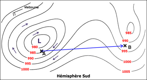
Question 216-8 : You are flying across northern canada on airway nca whiskey you wish to cross check the irs computed position by taking a bearing from a nearby vor you tune into the churchill vor and find you are on the 300° radial what is the bearing to plot on a chart if the variation at the vor is 2°w and the ?
298°.
Refer to figure to cross check our position using a chart we must find the true bearing from a known position to our aircraft in this case the known position is the churchill vor and we are on radial 300° radials from vors are in magnetic so we know the magnetic bearing from the vor to the aircraft is 300° m and also that we should use the variation at the vor to calculate our true bearing an easy way to remember this is that v is for vor and also for variation so use the variation at the vor there are many ways to turn this into a true bearing one of which is the rhyme variation east magnetic least variation west magnetic besttherefore our magnetic bearing of 300° is greater than our true bearing by the amount of 2° so the true bearing to plot from the vor on the chart would be 298° t note 1 another piece of information would still be required to compute the position of the aircraft such as another vor bearing or a dme readout note 2 in canada airspace northern domestic airspace nda is the area of compass unreliability within which runways and navaids are oriented to true north however churchill vor is not included in nda airspace as they would have to specify this in the question118° 304° 124°
Question 216-9 : A pilot is flying an ndb holding pattern they should continuously monitor the… ?
Morse code as a means to identify a potential failure of the ndb.
Ndb failure warningunline vor or ils systems that have failure warning indications the ndb does not warn the pilot in the case of a failure the ndb is a simple transmitter the adf receives the signal and displays the direction of the radio source since adf receivers do not have a 'flag' to warn the pilot when erroneous bearing information is being displayed the pilot should continuously monitor the ndb's identificationwhen the ndb itself fails the pilot might notice a searching needle on their display much like when it is out of range of the receiver this is not a very reliable failure indication so the pilot should continuously monitor the ndb's morse code identifier which would stop transmitting in the event of an ndb failure and would be a much more timely method of noticing a failure this is obviously not a nice thing to do as it is often a very annoying identifier noise another reason ndbs are such a bad navigational aid in modern timesAdf needle as a means to identify a potential failure of the ndb. adf warning flag(s) as a means to identify a potential failure of the ndb. atc frequency as a means to receive information about a potential failure of the ndb.
Question 216-10 : In the legend of a navigation chart a beacon is mentioned to be a tvor which description of the tvor is correct ?
A vor station with a shorter range used as part of the approach and departure structure at major aerodromes.
Vor applicationsvors can be classified as follow a conventional vor cvor is a first generation vor transmitter which emits a spinning limacon shaped amplitude modulating variphase signal a doppler vor dvor is a second generation vor transmitter with no moving parts and sends a frequency modulating variphase signal through its many antennas which circle the beacon to use the doppler shift effect a terminal vor tvor is a low power beacon with shorter range used as part of approach and departure procedures a broadcast vor is usually a terminal vor with a voice broadcast giving out the airfield weather atis superimposed on the carrier wave a test vor vot is a very low power beacon sited at some airfields it puts out a constant phase difference of zero in all directions this allows aircraft to test the accuracy of their equipment on the groundit is important to note with the other possible answers that the tvor in question is not just for the inbound runway course but is for all around the airfield and is useful for both approach and departurenote do not confuse a tvor with a test vorA terminal vor beacon used especially for aircraft on the final approach heading to the runway. a vor station that is emitting a signal to test vor indicators in an aircraft, and it is most commonly located at an aerodrome. a conventional vor beacon with an antenna that looks like a ‘’t’’ due to the horizontal and the perpendicular vertical parts.
Question 216-11 : Which of the following statements correctly describe the principles of operation of distance measuring equipment dme 1 the aircraft's primary radar output transmits a signal that triggers a reply from the dme station 2 a transmission from the aircraft's interrogator triggers a reply from the dme ?
2 and 3.
Distance measuring equipment dme is a type of secondary radar system that provides slant range using the pulse technique the aircraft’s interrogator transmits a stream of pseudo random omni directional pulse pairs on the carrier frequency of the ground station receiver the ground transponder then receives these interrogation pulses waits 50 microseconds and sends a reply repeating those pulse pairs outwards at a frequency 63 mhz above the interrogation frequencythe aircraft's dme system identifies its own unique stream of pulse pairs and measures the time of arrival electronically between the start of the interrogation and the reception of the ground transponder's replies this then can be calculated into a line of sight distance to the ground station known as the slant range3 and 4 1 and 2 2 and 4
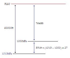
Question 216-12 : Determine the distance which will be shown on a dme display when the aircraft is at fl 360 and 6 nm plan range from the dme station for the calculation use the following assumptionsapproximations qnh is 1013 hpa pressure altitude is true altitude ?
8 nm.
Refer to figure the question states that we can regard pressure altitude to be the true altitude therefore true altitude equals 36 000 ft 36 000 ft 6 076 = 6 nm approx what we have is isosceles perpendicular triangle since plan distance and altitude are both equal to 6 nm dme measures the slant distance hypotenuse we already know lengths perpendicular of perpendicular sidesusing the pythagoras theorem x2 = 62 + 62 x2 = 72 x = 72 = 848 nm closest answer is 8 nm6 nm 10 nm 12 nm
Question 216-13 : A procedural vor approach using a procedure turn is to be flown the outbound leg follows the 098° radial from the vor to a dme range of 60 nm followed by a left turn onto a track of 018° m what should the next turn be ?
A right turn onto a track of 278° m to intercept the inbound track.
Refer to figure in a procedural approach often an aircraft will need to perform a reversal manoeuvre in order to get from an outbound to an inbound track there are many different ways this can be done and the chosen method will be dictated clearly on the approach plate some of the available methods are the 45 180 procedure turn the racetrack pattern the teardrop procedure and the 80 260 procedure turnicao doc 8168 322 reversal procedureb 80°260° procedure turn see figure i 4 3 1 b starts at a facility or fix and consists of 1 a straight leg with track guidance this straight leg may be timed or may be limited by a radial or dme distance 2 an 80° turn 3 a 260° turn in the opposite direction to intercept the inbound trackthe 80°260° procedure turn is an alternative to the 45°180° procedure turn a above unless specifically excludedA left turn onto a track of 233°(m) to intercept the inbound track. a right turn onto a track of 233°(m) to intercept the inbound track. a right turn onto a track of 198°(m) to intercept the inbound track.
Question 216-14 : After tuning the correct ils frequency and receiving the correct ident the pilot notice that the localiser loc and glide path gp indicators are both showing warning flags the pilot confirms that the aircraft is within the prescribed coverage area of the ils what is the most probable reason for the ?
The aircraft receives modulating frequencies of 90 and 150 hz at a rate of 0%.
Learning objective 06202050205 describe the circumstances in which warning flags will appear for both the loc and the gp absence of the carrier frequency absence of the modulation simultaneously the percentage modulation of the navigation signal reduced to 0when within the coverage area of the ils and receiving the ident that means that the carrier wave for the correct loc is definitely being received but showing flags for both loc and gs is not what you would expect in normal operation when flags are shown it is due to any of the items listed in the lo above or possibly due to the received signal being below a certain strength this narrows down the possible failures to a modulation problemalso the other possible answers are wrong as selected course does not affect ils signals or indication any more than full scale deflection within the coverage area shows exactly that full scale deflection an aircraft ahead of yours might cause a momentary change in the ils indication due to signal reflection but this woud be a tiny blip indeedAn incorrect course is selected on the obi or hsi. more than full scale deflections are indicated. another aircraft ahead, on the same ils approach, is disturbing the transmission.
Question 216-15 : After tuning and receiving a correct ident you become established on an ils and follow the approach on short final the localiser loc and glide path gp indications disappear and both show warning flags instead what is the most probable explanation for the warnings ?
The modulation of the 90 hz and 150 hz signals is 0%.
Learning objective 06202050205 describe the circumstances in which warning flags will appear for both the loc and the gp absence of the carrier frequency absence of the modulation simultaneously the percentage modulation of the navigation signal reduced to 0as we have identified and followed the ils down to short final by this point we know that this sudden appearance of flags is a fault of some kind when flags are shown it is due to any of the items listed in the lo above or possibly due to the received signal being below a certain strength this narrows down the possible failures to a modulation problemalso the other possible answers are wrong as the lack of locgp ident signals would not be a reason for showing flags loss of both carrier frequencies would cause this to happen but that is not one of the available answers there is no cone of confusion for ils transmitters and definitely should be no similar error regions on short final signal strength that is too high would not cause distortionLoss of both the loc and the gp identification transmissions. the aircraft is flying through the cone of confusion of the ils transmitters. signal strength increases to the point where it becomes distorted.
Question 216-16 : An aircraft is on the 290° radial from a nearby vor the magnetic variation at the vor is 5°e and the magnetic variation at the aircraft is 7°e what true track does the aircraft need to fly to go directly to the vor ?
115°.
The aircraft is on radial 290° which is a magnetic bearing from the vor to turn this into a true bearing we can use the saying variation west magnetic best variation east magnetic leastin this case we must use the variation at the vor as this is where the radials come from which is 5° east an easy way to remember this is that 'v' is for variation and vor so we should use the magnetic variation at the vormagnetic is least therefore the true bearing from the vor is going to be 5° more than 290° m so will be 295° t the bearing from vor to aircraft is 295° t so the true track to fly the opposite direction is 295 180 = 115° t this is the true track to be flown direct to the vor105° 297° 110°
Question 216-17 : An aircraft is radar vectored onto a cat i ils approach using a hsi the final approach track is 164° and the magnetic variation is 4°w the pilot is expecting approximately 6° right drift on final approach what should they set the course selector to on the hsi ?
164°.
An ils inbound track is based on magnetic courses and therefore there is no need to apply variation as the hsi horizontal situation indicator is also based on magnetic as it is slaved to the magnetic field by the remote reading compass systemit is also important to note that the hsi display will actually not depend on the selected course as an ils course deviation indicator cdi does not depend on selected course and just works off the differing modulation between two localiser lobes to give fly right or fly left indications the cdi in the middle of the hsi will just display fly left and fly right indications no matter the selected course and can therefore reverse sense if twisted backwards the hsi should therefore be set up with the inbound magnetic course selected as this will give the correct indications and an aide memoir of the inbound course to the pilot all the way down the approachthe inbound heading of the aircraft accounting for wind correction angle would not be used for many important reasons158° 160° 168°
Question 216-18 : Which of these options correctly describes the basic principles of operation of an mls ?
The time interval between the to and from scans in azimuth and elevation determines the aircraft position within the coverage area.
Refer to figure the principles of operation of microwaves landing systems mls are actually quite simple to understand there are 2 main and 1 extra transmitters providing information to the aircraft the first one provides information about how far an aircraft is horizontally from the correct inbound course called azimuth guidance similar to ils localiser the second one provides similar information about how far the aircraft is from the correct glide path called elevation guidancethere is a third transmitter that is used to allow curved and segmented mls procedures to take place also called the dmep which is a more precise version of a standard dme with this in use also the aircraft can have the knowledge of its 3 dimensional position for much more complex not straight in approachesthe azimuth and elevation transmitters work in the same way they emit a beam that scans the sky side to side to and fro for the azimuth guidance up and down for the elevation beam the aircraft then detects how much time passed inbetween the beams being detected between the to and the fro beam for instance and can very accurately detect its angular distance from the inbound courseglide paththe azimuth beam does not constantly scan to fro to fro but has a break whilst the elevation beam does it's own scan and they alternate with each other with data being passed also through the frequency at set intervals Guidance is given using the localiser and the glide path selected by the pilot, the guidance is based on the received and measured difference in depth of modulation (ddm). guidance is provided based on the pilots' selection of the transmitters providing the pilot with the required localiser and glide path. the distance between the to and from scans in azimuth and elevation determines the aircraft position, within the coverage area.
Question 216-19 : What is one of the main differences between cat ii and cat iii mls approaches ?
Only cat iii allows no decisions height.
Cat ii and cat iii minima are not specific to the mls microwave landing system but are much more commonly used on ils approaches as mls approaches barely exist anymore it can be thought of as a scale cat i can get an aircraft down to 200ft cat ii can get further down to 100 ft etc then there are 3 levels of cat iii minima which do actually have varying rvr requirements depending on authority but the annex above gives the basic valuesboth cat ii and cat iii require a radio altimeter and both have rvr requirements except cat iiic but this is only one section of cat iii minima so all the other answers are incorrectOnly cat iii requires a runway visual range. only cat iii requires a radio altimeter. only cat ii requires a runway visual range.
Question 216-20 : There are two primary methods of flying to or from an ndb complete the following statement from the options below 1 may be used to fly 2 the ndb while 3 may be used to fly 4 the ndb ?
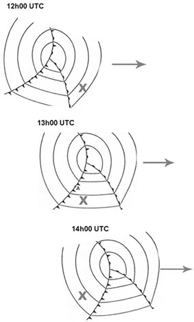
1 homing 2 to 3 tracking 4 to or from.
Refer to figure there are 2 different ways to fly using ndb's the difference between the two is how the wind is dealt within the 'easiest' way to fly homing the pilot can simply point at the ndb relative bearing 0º and keep the needle on the nose of the aircraft the problem is that the wind will push them off track if there is any crosswind but the aircraft will just change its heading to point at the ndb again meaning that they end up flying a curved path towards the beacon ending almost completely into wind this is not efficient and can cause dangers with terrain clearance and other traffic a visual representation can be seen in the annex abovetracking on the other hand is a more correct way to fly using an ndb and this requires the pilot to choose an inbound or outbound course from the beacon and maintain it by applying a wind correction angle to their heading so that their track is always directly towards or away from the ndb on the chosen radial it is a little more complex to fly but far more usefulnot that homing can only take you to an ndb whereas the tracking technique can guide aircraft to and from ndbs(1) the needle down method; (2) to or from; (3) the needle up method; (4) to (1) procedure turns; (2) to; (3) the track made good method; (4) to or from (1) homing; (2) to or from; (3) tracking; (4) to
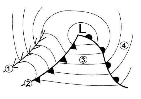
Question 216-21 : A crew is briefing for a procedural vor approach that requires a procedure turn for their destination airport this procedure turn consists of a straight track with outbound track guidance followed by a turn of 45° left followed by a ?
Timed straight leg without track guidance and a 180° turn to the right to intercept the inbound track.
Refer to figuresin a procedural approach often an aircraft will need to perform a reversal manoeuvre in order to get from an outbound track to an inbound track there are many different ways this can be done and the chosen method will be dictated clearly on the approach plate some of the available methods are the 45 180 procedure turn the racetrack pattern base turns and the 80 260 procedure turn the one in question has started with a 45º turn so must be the 45 180 procedure turn see the annexes above for the specific manoeuvre and the other main reversal proceduresicao doc 8168322 reversal procedure3223 a 45°180° procedure turn see figure ii 5 3 1 a starts at a facility or fix and consists of 1 a straight leg with track guidance this straight leg may be timed or may be limited by a radial or distancemeasuring equipment dme distance 2 a 45° turn 3 a straight leg without track guidance this straight leg is timed it is i 1 minute from the start of the turn for category a and b aircraft andii 1 minute 15 seconds from the start of the turn for category c d and e aircraft and4 a 180° turn in the opposite direction to intercept the inbound trackTimed turn to the left to intercept the inbound track. timed straight leg without track guidance and a 180° turn to the left to intercept the inbound track. 260° turn to the right to intercept the inbound track.
Question 216-22 : Which of the following options states the correct frequency band propagation path and frequency range for an ndb ?
Lf and mf surface waves 190 khz to 1750 khz.
Learning objective 06202020105 state that the ndb operates in the lf and mf frequency bandslearning objective 06202020106 state that the frequency band assigned to aeronautical ndbs according to icao annex 10 is 190 1750 khzlearning objective 06201030402 state that radio waves in lf mf and hf propagate as surfaceground waves and sky wavesthis question involves knowledge of all the above learning objectives there is not much more to explain except that ndbs are only properly usable when they travel as surface waves radio waves which cling to the surface of the earth this is because the direction of the incoming beam matters to their accuracy by their very nature and is much less accurate if it has been 'reflected' off the ionosphere it is for this reason that there is a 'night effect' when the sky waves reflect much more from the ionosphere and return to the aircraft interfering with the surface waves to cause difficulty in measurementsUhf only, space waves, 329.15 mhz to 335 mhz vhf only, ground waves, 108 mhz to 117.975 mhz. mf only, surface waves, 300 khz to 1750 khz.
Question 216-23 : A pilot of an aircraft flying in the daytime at fl80 on heading 030° m is instructed by atc to route directly towards an ndb the adf is already tuned to this ndb and identified correctly with a qdm of 340° m and about 8 nm away upon banking left to start a turn the indication on the rmi rapidly ?
Dip error.
Learning objective 06202020503 explain that the bank angle of the aircraft causes a dip errorwith the way that an adf antenna picks up the direction of the incoming signal there can be quite a significant error brought into the reading simply by banking the aircraft this is called dip error when tracking ndbs in real life dip error is actually quite large and means that the adf needle is almost useless whilst in the turn it is also very difficult to correct for accuratelyAntenna shadowing quadrantal error station interference
Question 216-24 : Ils approaches are divided into facility performance categories which of the following statements relates to facility performance category ii ?
Guidance is provided from the coverage limit to the point at which the localiser course line intersects the ils glide path at a height of 15 m 50ft or less above the horizontal plane containing the threshold.
Refer to figurelearning objective 06202050401 explain that ils approaches are divided into facility performance categories defined in icao annex 10icao annex 10 sets out facility performance categories in order to set out the requirements for cat i ii and iii approaches there are therefore facility performance category i ii and iii instrument landing systemsthe differences between the three facility performance categories are numerous everything from the accuracy down to the monitoring is defined for all three facility performance categories with many more variables in between in the end that means that they can provide increasingly good guidance to aircraft as the category goes up and the associated minima get lower as you can see in the annex above taken directly from icao annex 10 facility performance category i can give guidance down to a height of 100 ft or less category ii down to 50 ft or less and category iii down to the runway with the aid of ancillary equipment it is important to note that the facility performance categories do not use the same altitudes at the ils categories we use in normal operations a facility performance category i ils system is capable of providing information for a cat i ils as it gives useful information down to 100ft which is lower than the lowest minimums of a cat i ils at 200ft this gives some safety margin in the system which is always useful at such extremely low heightsGuidance is provided from the coverage limit to the point at which the localiser course line intersects the ils glide path at a height of 60 m (200 ft) or less above the horizontal plane containing the threshold. it is an ils which, with the aid of ancillary equipment when necessary, provides guidance from the coverage limit down to and along the runway. it proves guidance from the coverage limit to the point at which the localiser course line intersects the ils glide path at a height of 30 m (100 ft) or less above the threshold.
Question 216-25 : What causes the dip error in an adf ?
The tilted antenna whilst banking the aircraft.
Learning objective 06202020503 explain that the bank angle of the aircraft causes a dip errorwith the way that an adf antenna picks up the direction of the incoming signal there can be quite a significant error brought into the reading simply by banking the aircraft by doing this the antenna is no longer level so is now detecting a downwards component of the signal which effects the reading in a similar way to tilting a compass this is called dip error when tracking ndbs in real life dip error is actually quite large and means that the adf needle far less accurate whilst in the turn it is also a very difficult eerror to correct for accuratelyThe unbalanced rm indicator needle. signals being re-radiated from the metal fuselage. the combined dip angle of the earth's magnetic field.
Question 216-26 : Which frequency band do dmes operate within ?
Ultra high frequency uhf 300 mhz to 3000 mhz.
Refer to figure learning objective 06202040101 state that dme operates in the uhf bandeach frequency band is effectively a logarithmic band which begins at one frequency value and ends at the frequency value 10x higher they all begin with the number 3 and are of different orders of magnitudedmes operate within uhf ultra high frequency which is the band above the well known vhf frequency band therefore a good way of remembering the frequency bands is having vhf as a starter band and we can say that a well known vhf frequency of 1215 mhz is between 30 and 300 mhz so therefore we can create the bands above and below that and so onthere is an acronym to remember the order using the first letters very lovely maidens have very useful sewing equipment High frequency (hf): 3 mhz to 30 mhz ultra high frequency (uhf): 30 mhz to 300 mhz very high frequency (vhf): 30 mhz to 300 mhz
Question 216-27 : Given the following information what is the true bearing from the ndb to the aircraft compass heading 348º adf indication relative bearing indicator 317º deviation 2º variation 22ºw the convergence is negligible ?
101º t.
Refer to figurefirst we must calculate our true heading then we can use our relative bearing to calculate our true bearing from the ndb sometimes called a qte to calculate our true heading we can use the saying 'cadbury's dairy milk very tasty' which is popular within british aviation schools also an option is tv makes dumb children which is a reversal of the other saying there is a universal method which can be used that applies to both directions compass deviation magnetic variation trueto get our compass heading into a magnetic heading we apply the deviation using the rhyme deviation west compass best deviation east compass leastwe must also know that a positive value is easterly and a negative value is westerly it can be given in either format so in this case our compass heading is 2º more than our magnetic heading so our magnetic heading is 348º 2º = 346ºnow to get true heading we apply variation to our magnetic value using the rhyme variation west magnetic best variation east magnetic leastwe now know that our magnetic heading is 22º more than our true heading so true heading = 346º 22º = 324ºwith this in mind we can apply the relative bearing to our true heading which is simply a case of adding the two togethertrue heading + relative bearing = 324º + 317º = 641º which isn't possible so subtract 360º > 281º281º is therefore the true bearing from the aircraft to the ndb we want to find the opposite direction to this so we shall simply add or subtract 180º giving us 101º true bearing from the ndb to the aircraftnote even though this does look like a gnav or fpl question the feedback shows that it has been asked in rnav and the rnav learning objectives include specific references to the topics 06202020202 06202020204 and 06202020205 everything required for this question is in the rnav syllabus145º (t) 125º (t) 105º (t)
Question 216-28 : An aircraft equipped with a vhf radio is flying within radio range of two or more ground direction finding stations which aircraft parameter can be determined in this scenario the aircraft's ?
Position.
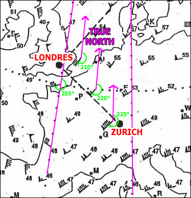
Learning objective 06202010203 explain that by using more than one ground station the position of an aircraft can be determined and transmitted to the pilotvdf vhf direction finding is a method of measuring the direction from which a vhf signal came it has been used for many decades now and is particularly useful as the transmitting aircraft only needs a standard vhf radio to ask for a vdf bearing from a suitably equipped atsu this can give them qdm magnetic bearing from the aircraft to the station qdr magnetic bearing from the station to the aircraft quj true bearing from the aircraft to the station qte true bearing from the station to the aircraftwith this information the pilots can plot the location of their aircraft on a chart by drawing a true radial qte outbound from each station that was used 2 stations and therefore 2 lines can be enough to calculate the position of an aircraft by finding the point at which they intercept this is a process known as triangulation it is important to get a large angle at the point of interception as the larger the angle optimum 90º the better the precision of the fix more than 2 vdf stations can also be used to get a more accurate fixdistress and diversion 1215 mhz have access to an auto triangulation feature which gives them an immediate readout of the position of any calling aircraft due to the reception of its transmission at multiple different locations with vdf capabilityposition is the only thing that can be gained from vhf direction finding though so it is limited in that sense but is very useful in the sense that only a vhf radio is required in the aircraftAltitude tas heading
Question 216-29 : A cat i ils with a decision height of 240 ft is what type of approach ?
Type b 3d approach.
Icao annex 6 part ii 22222 instrument approach operations shall be classified based on the designed lowest operating minima below which an approach operation shall only be continued with the required visual reference as follows a type a a minimum descent height or decision height at or above 75 m 250 ft andb type b a decision height below 75 m 250 ft type b instrument approach operations are categorized as 1 category i cat i a decision height not lower than 60 m 200 ft and with either a visibility not less than 800 m or a runway visual range not less than 550 m 2 category ii cat ii a decision height lower than 60 m 200 ft but not lower than 30 m 100 ft and a runway visual range not less than 300 m 3 category iii cat iii a decision height lower than 30 m 100 ft or no decision height and a runway visual range less than 300 m or no runway visual range limitations this is new from 2018 and categorises instrument approaches into type a or type b depending on their decision height or minimum descent height being above or below 250ft as the approach in question is an ils which has both horizontal and vertical guidance it is therefore a 3 dimensional 3d approach and its decision height is below 250 ft so it is type b note this question does cross over quite heavily with air law but feedback shows that it is being asked in rnav examsType b, 2d approach type a, 2d approach type a, 3d approach
Question 216-30 : Which of the following statements is true ?
With an a2a modulated wave you can hear the wave in adf mode.
Refer to figures the first annex above contains the 4 learning objectives which relate to this question2 different types of ndb exist and they are categorised by their radio wave modulation the earlier type of ndb is called n0n a1a and the newer type is n0n a2a the only difference between the two is that a1a signals can not be identified unless the bfo beat frequency oscillator mode is used whereas a2a signals can be identified aurally in standard adf mode as well the reasons behind this are slightly too complex for the syllabus and most modern adf panels use the bfo mode automatically when required anywayWith an a1a modulated wave you can hear the wave in frq mode. with an a2a unmodulated wave you can hear the wave in bfo mode. with n0n modulated wave you can hear the wave in bfo mode.
Question 216-31 : An aircraft is equipped with a dme receiver that can provide a read out of ground speed it is climbing on a heading of 270° t and is crossing the 330 radial from a vordme station the ground speed calculated by the dme computer is ?
Less than the actual ground speed because the change in slant range is smaller than the change in ground distance.
Refer to figure some dme receivers have a setting that will read out the aircraft's groundspeed when heading towards or away from the station as well as an estimate of the time to the station this is calculated by the dme receiver using the rate of change of the detected distance from the station this means that flying anywhere other than directly tofrom the station causes an unusable read out as is the case in this question where we are crossing the radialsanother thing to consider is that dme systems calculate slant range from the aircraft to the station so the dme groundspeed calculations are more accurate when this slant range closely resembles ground distance so when at low altitude and far away from the dme within line of sight of course in this question our aircraft is crossing the 330 radial and the slant distance is increasing a small amount but by much less than our groundspeed therefore the groundspeed read out on our dme will be lower than our actual groundspeedInaccurate because the aircraft is moving away from the station and the slant range error becomes more significant with distance. greater than the actual ground speed because the change in slant range is greater than the change in ground distance. exactly correct because the aircraft slant range is increasing at the ground speed due to the climb.
Question 216-32 : A pilot has selected the appropriate ils frequency for the approach that they are currently established on which of the following scenarios would cause a warning flag to appear on both the localiser loc and giide path gp indications ?
Absence of both carrier waves.
Learning objective 06202050205 describe the circumstances in which warning flags will appear for both the loc and the gp absence of the carrier frequency absence of the modulation simultaneously the percentage modulation of the navigation signal reduced to 0when on the approach the sudden appearanc of both flags must mean a fault of some kind not just being out of range so this must be down to one of the faults listed in the learning objective above the easiest fault to remember is correct in this case as the sudden absence of a carrier wave is certainly going to remove loc and gp indications and will therefore show warning flagsthe other answers are wrong because the difference in depth of modulation ddm is the way an ils tells you where you are in relation to the localiser centreline or the glide path and a ddm of zero means being exactly on the loc or gp 'excessive loc or gp deviations' is vague but even when at more than full scale deflection but within the coverage area the indicators still show the direction we are off trackglidepath loss of ident transmission would not show flags on its own but there might be a common error which causes both flags to show and the ident to stop transmitting such as a total power loss etcA difference in depth of modulation of zero. excessive loc and gp deviations. loss of ils ident transmission.
Question 216-33 : To avoid the inaccuracies that may be caused by coastal refraction the pilot should attempt to take adf bearings when… ?
The aircraft is on the perpendicular to the coast which runs through the ndb.
Refer to figure learning objective 06202020401 explain 'coastal refraction' as a radio wave travelling over land crosses the coast the wave speeds up over water and the wave front bendscoastal refraction affects ndbadf equipment due to the type of carrier wave that ndbs transmit they transmit between 190 and 1750 khz which is partly in the lf band and partly in the mf band these waves travel as surface waves which are massively affected by the surface they are travelling over water is much smoother to travel over than land so the waves are able to travel a bit fasterthis creates a change in speed when ndb carrier waves go from land to sea which can cause a process called refraction meaning that the beam bends away from the perpendicular called the normal and therefore creates the image shown in the annex this means that the carrier wave arrives at our aircraft from a slightly different direction than it should and our adf therefore reads incorrectlythe best way to stop this is to place ndbs very close to the coast thereby reducing the error or to take adf readings when the signal crosses the coast at a right angle perpendicular the closer to the perpendicular the less refraction will occur and so is less affected by the coastal effectThe relative bearing is either 090º or 270º. the aircraft is situated on any perpendicular to the coast. the relative bearing is perpendicular to the true heading.
Question 216-34 : Which of the following options can be used for entry into a holding pattern based on a vordme fix ?
The dme arc defining the fix.
Note the feedback strongly suggests that this is a question asked in previous rnav exams even though there are no learning objectives within the rnav syllabus that pertain to itit is more of an air law question and even then it is on the edge of learning objective 01006050110the good thing is that it is a very distinctive question that will be easy to remember for the examrefer to figuresthere are a few different places a holding pattern can be constructed over ndbs vors over a vordme fix or over an rnav waypoint not a conventional nav aid the most complex of those is certainly the vordme fixtechnically a hold can be placed on 2 intersecting radials but they are extremely rarein the 1st annex above stockholm arlanda overview of all holding patterns there are all the different types of holds shownstarting from the top you can see hammar hmr vor and there is a hold there with the inbound course of 191° and left turns and 15 minute legs usually 1 min legs are used but this is a higher altitude hold below this is the erken erk ndb hold based directly on the ndbto the far left of the chart is the tinka hold which is simply based on an rnavrnp waypointthe furthest south holding pattern nilug is a hybrid it is an rnav waypoint but with a vordme fix given so that it can be flown using conventional nav aidsthis is what the question is asking aboutthere are 3 more of these on the chart eltok balvi and xilanfirstly note that all these vordme holds all have inbound courses directly towards the vor this is so the inbound course can always be tracked which is a key requirement of any holding pattern technically they can also track directly away from the vor but i have never seen one published in the case of the nilug hold the pilot will fly inbound on the 007° to course radial 187 towards tebby teb vor until reaching a dme distance of 442 nm then begin the right hand turn and do the rest of the procedure using timings which is very normal until established on the inbound course again where tracking resumes until 442d etcthey are easy enough to fly if a little inaccurate due to being so far from the vor the difficulty arrives due to the fact that they can only be joined from particular directionsas can be seen in the annex above they can only be joined using conventional nav aids from a the vor radialb the dme arc where specified orc the entry radial to a vordme fix at the end of the outbound leg as publishedby far the most common way and easiest is by the vor radial but that is not one of the available options so we have to say the dme arc defining the fix in this case 442 nm see the 2nd annex for a view of the dme arc for this exampleThe entry radial to the start of the inbound leg. tracking to the vor. any track into the vor/dme fix.
Question 216-35 : What causes 'mountain effect' and what type of navigational aid does it affect ?
It is caused by diffraction and affects ndbs.
Learning objective 06202020501 ndb section describe diffraction of radio waves in mountainous terrain mountain effect because ndbs produce lf and mf radio waves which travel primarily as surface ground waves for the purposes of directional navigation as is required for ndbs the ground that is being travelled over matters a lot water is flat for instance so surface waves travel over water faster and much further than a similar strength wave travelling over rolling hills built up areas and worst mountainous terrain basically the more obstacles and rougher the terrain the worse the ndb signals travelthis is most prominent in mountainous terrain as the radio waves try and follow the contours of the ground which means going over the peaks and into the valleys the largest problem with this is a phenomenon known as diffraction where the wave gets scattered slightly as it crests each mountain and tries to go down the other side reflection of the waves also could be an issue but does not affect ndb directions received by aircraft as much as the relative diffraction of mountainsIt is caused by refraction and affects ndbs. it is caused by diffraction and affects vors. it is caused by refraction and affects vors.
Question 216-36 : You are established on an ils approach at 4 nm on the dme and get some signal interference what could be the reason for this ?
Multipath interference from reflections off objects within the published coverage area.
Learning objective 06202050408 explain that multipath interference is caused by reflections from objects within the ils coverage areawe can be sure that the aircraft is within the coverage area in this question as it is fully established on the ils approach at 4 nm it is most likely to be descending on the glide path as well as on the localiser this leaves only one answer available as none of the other options happens when within the correct coverage area of the ilsreflections of the ils signals off objects can hit the aircraft at certain stages of the approach altering the difference in depth of modulation between the 90 hz and the 150 hz lobes and can cause a false movement of the ils needles which in turn can affect the autopilot if one is engagedYou get interference because of being outside the published coverage area. reverse-sensing side lobes. picking up the 'false glide slope'
Question 216-37 : You are flying on radial 227° inbound to a vor the wind is from 270° and the wind correction angle is 3° the magnetic variation is 10°w the obs should be set to 1 and magnetic heading should be 2 ?
1 047° 2 044°.
If we are flying inbound on the 227° radial then our track has to be the opposite 047° 047° is therefore what we also want to set as our obs course as we want the needle to indicate in the correct sense as we track to the vor the wind in this scenario is coming from 270° it does not matter whether true or magnetic which is a partial tailwind blowing across from the left this means that we have to turn left by our wind correction angle 3° to track 047° this gives us a heading of 044° to flyall our bearings and tracks are in magnetic as this is what is used by vors and the wind does not matter as 10° different would still make the wind a tailwindcrosswind from the left(1) 227°; (2) 230° (1) 047°; (2) 047° (1) 237°; (2) 233°
Question 216-38 : A doppler vor provides usable signals up to what distance from the station and is intended for which type of traffic ?
Up to 200 nm from dvor for en route ifr traffic.
Learning objective 06202030104 state that the following types of vor are in operation conventional vor cvor a first generation vor station emitting signals by means of a rotating antenna doppler vor dvor a second generation vor station emitting signals by means of a combination of fixed antennas utilising the doppler principle en route vor for use by ifr traffic terminal vor tvor a station with a shorter range used as part of the approach and departure structure at major aerodromes test vor vot a vor station emitting a signal to test vor indicators in an aircraftas stated in the learning objective above dvors are powerful enough to be used by en route ifr aircraft for reliable navigation by looking in the enr section of an aip the useful ranges of the vors can be seen and the maximum is 200 nm distance and 50 000 ft altitudeUp to 100 nm from dvor for military ifr traffic. up to 75 nm from the terminal area for all traffic within the control zone. up to 25 nm from the approach area for traffic following lnav approaches.
Question 216-39 : When tuned in to an ndb when is dip error most likely to occur ?
When turning towards the ndb.
Learning objective 06202020503 explain that the bank angle of the aircraft causes a dip errordip error is an inaccurate reading of the bearing information when the aircraft is banked this is because the adf system that receives and interprets ndb signals was designed to work when in horizontal flight when a turn is initiated the indicated bearing is modified the needle will cause an error towards the direction of whichever wing is banked downWithin the ndb's cone of confusion. when tracking or homing to the ndb with a crosswind. when flying directly away from the ndb.
Question 216-40 : When holding at an ndb you are approaching the beacon on the inbound leg how will you know when to initiate the turn ?
The head of the needle will be pointing to the fix and the needle will turn 180° when passed it.
Refer to figurea holding pattern requires an aircraft to fly towards the holding fix on a certain inbound track and when the aircraft reaches the fix vor ndb or a vordme fix the pilots should begin a 180º turn right is standard but left turns can be used upon the end of this turn or passing abeam the beacon the pilot will then fly a timed leg on the opposite track plus any wind correction to the inbound leg now called the outbound leg then turn back onto the inbound leg to start the process again this forms the familiar racetrack patternan ndb simply produces a signal of particular frequency and the adf receiver in our aircraft picks this up and tells us from where it came this is very simple and means we can follow an adf needle all the way to the beacon when it will then become very sensitive and go from pointing ahead of the aircraft to pointing behind it as per the location of the ndbthis is different from a vor which we would track inbound via a cdi course deviation indicator which flicks from to to from upon passing the beacon and also has a cone of confusionThe head of the needle will be pointing away from the fix and the needle will turn 180° when passed it. the to indication will become a from indication after passing the fix. the indicator will go from full left deflection to full right deflection when passing the fix.
Exclusive rights reserved. Reproduction prohibited under penalty of prosecution.