A free Premium account on the FCL.055 website! Read here
Sign up to unlock all our services and 15164 corrected and explained questions.
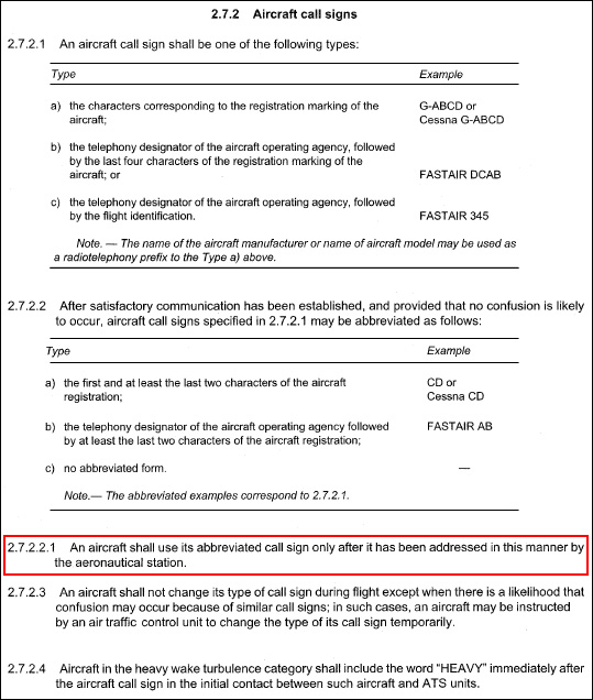
Question 10-1 : An aircraft registered in france is executing a flight from paris france to santiago chile when should the aircraft follow the european rules of the air sera ? [ Explanation maintenance ]
All the time except when the sera regulations conflict with those from the state overflying
Question 10-2 : A circling approach is ?
A visual flight manoeuvre keeping the runway in sight.
Doc 8168 chapter 7 visual manoeuvring circling area 71 purpose72 visual flight manoeuvre721 a circling approach is a visual flight manoeuvre each circling situation is different because of variables such as runway layout final approach track wind velocity and meteorological conditionstherefore there can be no single procedure designed that will cater for conducting a circling approach in every situation722 after initial visual contact the basic assumption is that the runway environment should be kept in sight while at minimum descent altitudeheight mdah for circling the runway environment includes features such as the runway threshold or approach lighting aids or other markings identifiable with the runwayA visual manoeuvre to be conducted only in imc. a flight manoeuvre to be performed only under radar vectoring. a contact flight manoeuvre.
Question 10-3 : Abbreviations what does the abbreviation ois mean doc 8168 ?
Obstacle identification surface.
Ois obstacle identification surfaceObstacle in surface. obstacle identification slope. obstruction in surface.
Question 10-4 : At fl 110 the maximum speed at which an aircraft can enter a holding pattern is ?
230 kt ias.
Doc 8168 aircraft operations icao maximum holding speeds up to 14000 ft 230 kt14000 ft to 20000 ft 240 kt20000 ft to 34000 ft 265 ktabove 34000 ft m 083240 kt ias. 230 kt tas. 240 kt tas.
Question 10-5 : A descent or a climb conducted in a holding pattern is called ?
A shuttle.
Icao doc 8168 338 shuttle a shuttle is normally prescribed where the descent required between the end of initial approach and the beginning of final approach exceeds the values shown in table i 4 3 1note a shuttle is descent or climb conducted in a holding pattern A procedure turn. a base turn. a race track.
Question 10-6 : An approaching aircraft may descent below the msa if ?
All mentioned answers are correct.
When in imc you should not descend below msa minimum sector altitude as on the chart until established in the approach or hold procedure as the safe altitude is based on correct entry procedure it will cover a certain aera of groundyou may descend on radar vectors in accordance with a published approach procedure or if you have the field and the underlying terrain in sight and you will keep it in sightThe pilot has the field and the underlying terrain in sight and will keep it in sight. the aircraft gets radar vectors. the pilot is following the published approach procedure.
Question 10-7 : Approach procedures arrival and approach segments intermediate approach segmentwhat is the minimum obstacle clearance requirement at the end of the primary area of the intermediate approach segment in an instrument approach procedure ?
300m 984 ft reducing to 150 m 492 ft .
Doc 8168 chapter 4 intermediate approach segmentthis is the segment during which the aircraft speed and configuration should be adjusted to prepare the aircraft for final approach for this reason the descent gradient is kept as shallow as possibleduring the intermediate approach the obstacle clearance requirement reduces from 300 m 984 ft to 150 m 492 ft in the primary area reducing laterally to zero at the outer edge of the secondary area 714150m (492 ft) reducing to 0 m. 450m (1476 ft) reducing to 150 m (492 ft). 300 m (984 ft) reducing to 0 m.
Question 10-8 : Approach procedures circlingit is permissible to eliminate from consideration a particular sector where a prominent obstacle exists in the visual manoeuvring circling area outside the final approach and missed approach area when this option is exercised the published procedure ?
Prohibits circling within the total sector in which the obstacle exists.
A visual maneuvering circling area is the area in which the obstacle clearance should be taken into consideration for aircraft carrying out a circling approach icao it is the visual phase of flight after completing an instrument approach to bring an aircraft into position for landing on a runway not suitably located for a straight in approach the visual maneuvering area for a circling approach is determined by drawing arcs centered on each runway threshold and joining those arcs with tangent lines the radius of the arcs is related to the aircraft category the speed for each category the wind speed 25 knots 46 kmh is taken throughout the turn and the bank angle 20° average or 3°s whichever requires less bank it is permissible to eliminate from consideration a particular sector where a prominent obstacle exists in the visual maneuvering circling area outside the final approach and missed approach area when this option is exercised the published procedure prohibits circling within the total sector in which the obstacle existsPermits circling only in vmc. recommends not to perform circling within the total sector in which the obstacle exists. prohibits the circling approach to the affected runway.
Question 10-9 : Approach proceduresthe term used to describe the visual phase of flight after completing an instrument approach to bring an aircraft into position for landing on a runway which is not suitably located for straight in approach is ?
Visual manoeuvring circling .
Doc 8168 chapter 7 visual manoeuvring circling area 71 purpose711 visual manoeuvring circling is the term used to describe the phase of flight after an instrument approach has been completed it brings the aircraft into position for landing on a runway which is not suitably located for straight in approach ie one where the criteria for alignment or descent gradient cannot be metContact approach. aerodrome traffic pattern. visual approach.
Question 10-10 : Approach procedures final approach segmentin a precision approach ils generally glide path interception occurs at heights above runway elevation from ?
Half a scale deflection after being established on the track.
Doc 8168 chapter 5 final approach segment this is the segment in which alignment and descent for landing are made final approach may be made to a runway for a straight in landing or to an aerodrome for a visual manoeuvre555 protection of the precision segment5551 the width of the ilsmlsgbas final approach protection area is much narrower than those of non precision approaches descent on the glide pathmls elevation angle must never be initiated until the aircraft is within the tracking tolerance of the localizerazimuth5552 the protection area assumes that the pilot does not normally deviate from the centre line more than halfscale deflection after being established on track thereafter the aircraft should adhere to the on course on glide pathelevation angle position since a more than half course sector deflection or a more than half course fly up deflection combined with other allowable system tolerances could place the aircraft in the vicinity of the edge or bottom of the protected airspace where loss of protection from obstacles can occurOne full scale deflection after being established on the track. a quarter of a scale deflection after being established on the track. one and a half of a scale deflection after being established on the track.
Question 10-11 : Approach procedures final approach segmentin a precision approach ils the final approach segment begins at the ?
Fap.
Final approach that part of an instrument approach procedure which commences at the specified final approach fix or point or where such a fix or point is not specifieda at the end of the last procedure turn base turn or inbound turn of a racetrack procedure if specified orb at the point of interception of the last track specified in the approach procedure andends at a point in the vicinity of an aerodrome from which 1 a landing can be made or2 a missed approach procedure is initiated 715 doc 8168 for a precision approach ils mls etc the final approach segment begins at the final approach point fap this is a point in space on the final approach track where the intermediate approach altitudeheight intercepts the nominal glide pathmicrowave landing system mls elevation anglefinal approach fix faf refers to a non precision approachFaf. map. if.
Question 10-12 : Approach procedures instrument approach areathe primary area of an instrument approach segment is ?
A defined area symmetrically disposed about the nominal flight track in which the minimum obstacle clearance is provided.
Doc 8168 volume 1 chapter 1 definitions primary area a defined area symmetrically disposed about the nominal flight track in which full obstacle clearance is provided secondary area a defined area on each side of the primary area located along the nominal flight track in which decreasing obstacle clearance is provided13 areas131 where track guidance is provided in the design of a procedure each segment comprises a specified volume of airspace the vertical cross section of which is an area located symmetrically about the centre line of each segmentthe vertical cross section of each segment is divided into primary and secondary areas full obstacle clearances are applied over the primary areas reducing to zero at the outer edges of the secondary areas see figure i 2 1 2 132 on straight segments the width of the primary area at any given point is equal to one half of the total widththe width of each secondary area is equal to one quarter of the total width133 where no track guidance is provided during a turn specified by the procedure the total width of the area is considered primary area134 the minimum obstacle clearance moc is provided for the whole width of the primary area in the secondary area moc is provided at the inner edges reducing to zero at the outer edges see figure i 2 1 2 716The first part of the segment. the most critical part of the segment where the minimum altitude should be kept very carefully. the outside part of the segment where the obstacle clearance increases from 0 ft to the appropriate minimum.
Question 10-13 : Approach procedures mdh ochfor a non precision or circling approach the minimum descent height mdh cannot be lower than ?
The obstacle clearance height och .
Icao doc 8168 mdh minimum descent heightoch obstacle clearance height200 ft. 350 ft. 400 ft.
Question 10-14 : Approach procedures minimum sector altitudes msaminimum sector altitudes are established for each aerodrome the msa provides an obstacle clearance of at least 300 m 1000 ft within a circle associated with the homing facility for the approach procedure of that aerodrome how many nm is the radius of ?
25 nm.
Iaco doc 8168 minimum sector altitude the lowest altitude which may be used which will provide a minimum clearance of 300 m 1000 ft above all objects located in an area contained within a sector of a circle of 46 km 25 nm radius centred on a radio aid to navigationmsa on a final approach plate 717msa is centered on dus vor10 nm. 20 nm. 5 nm.
Question 10-15 : Approach procedures missed approach phasesa complete missed approach procedure consists of the following phases ?
Initial intermediate and final.
Img715after having completed the missed approach procedure you will have to restart the approach at the initial approach fix iaf Initial and final. arrival, initial, intermediate and final. arrival, intermediate and final.
Question 10-16 : Approach procedures missed approach climbnormally the missed approach procedures are based on a nominal missed approach climb gradient of ?
25%.
Icao doc 8168 aircraft operations chapter 6 6171 normally procedures are based on a minimum missed approach climb gradient of 25%2%. 5%. 3.5%.
Question 10-17 : Approach procedures non precision straight in a so called 'straight in approach' is considered to be acceptable for a non precision approach if the angle between the final approach track and the runway centreline is ?
30° or less.
Icao doc 8168 12 instrument approach procedure123 types of approach1231 there are two types of approach straight in and circling1232 straight in approachwherever possible a straight in approach will be specified which is aligned with the runway centre line in the case of non precision approaches a straight in approach is considered acceptable if the angle between the final approach track and the runway centre line is 30° or less40° or less. 20° or less. 10° or less.
Question 10-18 : Approach procedures arrival and approach segmentsthe minimum obstacle clearance in the primary area of the initial approach segment for an instrument approach procedure is at least ?
300m 984 ft .
Doc 8168 chapter 3 initial approach segment 313 minimum obstacle clearancethe initial approach segment provides at least 300 m 984 ft of obstacle clearance in the primary area reducing laterally to zero at the outer edge of the secondary area 714150m (492 ft). 450m (1476 ft). 600m (1968 ft).
Question 10-19 : Approach segments in an instrument approach procedure the segment in which alignment and descent for landing are made is called ?
Final approach segment.
The final approach segment is the segment in which alignment and descent for landing are made the final approach may be made to a runway for a landing or to an aerodrome for a visual manoeuvre for a straight in approach angle formed by the final approach track and the runway centre line must not exceed 30° for procedure restricted to cat a and b aircraft only and 15° for other aircraft categories 714Initial approach segment. intermediate approach segment. arrival segment.
Question 10-20 : Arrival and approach segments generalwhat are the names of all separate segments that can be part of an instrument approach procedure ?
Arrival initial intermediate final missed approach.
Question 10-21 : Altimeter setting proceduresthe transition from altitude to flight level and vice versa is performed ?
At the transition altitude during climb and at the transition level during descent.
When passing through the transition layer you must report your vertical position as an altitude your altimeter setting is now local qnh example in descent if transition layer is at 5000 ft 'speedbird 123 descending from flight level 100 to altitude 4000 ft qnh'in climb you must report your vertical position as a flight level while crossing the transition altitude your altimeter setting is now 1013 hpa At the transition level during climb, and at the transition altitude during descent. only at the transition altitude. only at the transition level.
Question 10-22 : Circling approachone of the conditions to descent below the mda on a circling approach is ?
The required visual references have been established and can be maintained.
You must have visual contact with the airport before attempting a circle to land maneuver and you must maintain visual contact with the airport at all times while circling to land 719circling approachThe landing runway and an alternative landing possibility (runway) are in sight. the horizontal visibility is at least 5 nm and the ceiling is 1500 ft or higher. the ceiling is 1500 ft or higher.
Question 10-23 : Definitions icao doc 8168 what is a turn executed by the aircraft during the initial approach between the end of the outbound track and the beginning of the intermediate or final approach track the tracks are not reciprocal ?
Base turn.
Doc 8168 720base turn consisting of 1 a specified outbound track and timing or dme distance from a facility followed by 2 a turn to intercept the inbound trackthe outbound track andor the timing may be different for the various categories of aircraft where this is doneseparate procedures are publishedProcedure turn. race track. reversal procedure.
Question 10-24 : Definitionswhat is a manoeuvre in which a turn is made away from a designated track followed by a turn in the opposite direction to permit the aircraft to intercept and proceed along the reciprocal of the designated track is called a ?
Procedure turn.
Img721Base turn. race track. reversal track.
Question 10-25 : Departure procedure designthe main factors that dictates in general the design of an instrument departure procedure isare ?
The terrain surrounding the aerodrome.
Atc availability and requirements. availability of navigation aids. airspace restrictions applicable and in force.
Question 10-26 : Dependent parallel approaches may be conducted to parallel runways provided that the missed approach track for one approach diverges by ?
At least 30° from the missed approach track of the adjacent approach.
Pans atm doc4444 6736 requirements and procedures for segregated parallel operations67361 segregated parallel operations may be conducted on parallel runways provided a the runway centre lines are spaced by the distance specified in annex 14 volume i andb the nominal departure track diverges immediately after take off by at least 30 degrees from the missed approach track of the adjacent approach see figure below 722At least 45° from the missed approach track of the adjacent approach. at least 25° from the missed approach track of the adjacent approach. at least 15° from the missed approach track of the adjacent approach.
Question 10-27 : Final approach segmentduring a precision approach ils glide path interception occurs normally at heights above runway elevation between ?
300 m 1000 ft to 900 m 3000 ft .
Typically glide path mls elevation angle interception occurs at heights from 300 m 1000 ft to 900 m 3000 ft above runway elevation in that case on a 3° glide path mls elevation angle interception occurs between 6 km 3 nm and 19 km 10 nm from the threshold doc 8168 542 final approach length5421 the intermediate approach altitudeheight generally intercepts the glide pathmls elevation angle at heights from 300 m 1 000 ft to 900 m 3 000 ft above runway elevation in this case for a 3° glide path interception occurs between 6 km 3 nm and 19 km 10 nm from the threshold300 m (1000 ft) to 600 m (1968 ft). 150 m (500 ft) to 300 m (1000 ft). 150 m (500 ft) to 900 m (3000 ft).
Question 10-28 : Holding procedures buffer areahow far beyond the boundary of the holding area extends the buffer area ?
5 nm.
Doc 8168 holding area the holding area includes the basic holding area and the entry area the basic holding area is the airspace required for a holding pattern at a specific level based on the allowances for aircraft speed wind effect timing errors holding fix characteristics etc the entry area is the airspace required for the entry procedure 723buffer area an additional buffer area extends 93 km 50 nm beyond the boundary of the holding area significant obstacles in the buffer area are taken into consideration when determining the minimum holding level3 nm. 5 km. 3 km.
Question 10-29 : Holding procedures entryrelated to the three entry sectors in a holding pattern there is a zone of flexibility on either side of the sectors boundaries of ?
5°.
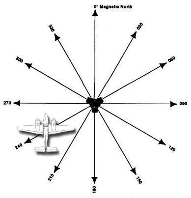
Doc8168 pans atm chapter 1 holding criteria14 entry141 the entry into the holding pattern shall be according to heading in relation to the three entry sectors see figure below recognizing a zone of flexibility of 5° on either side of the sector boundaries 724sector 1 parallel entrysector 2 offset entrysector 3 direct entry 725example zone of flexibility on either side of the boundaries of a parallel entry sector10°. 15°. 20°.
Question 10-30 : Holding procedures offset entryabove 14000 ft in still air the outbound time on a 30° offset track is limited to ?
1 minute 30 seconds.
Icao doc8168 149 timedistance outboundthe still air time for flying the outbound entry heading should not exceed a one minute if at or below 4 250 m 14 000 ft orb one and one half minutes if above 4 250 m 14 000 ft 727where dme is available the length of the outbound leg may be specified in terms of distance instead of time1 minute. 2 minutes. 3 minutes.
Question 10-31 : Holding procedures entry you have received instructions to hold over a radio fix the published procedure is all turns to the right 1 minute outbound inbound magnetic track 052° you are approaching the fix on magnetic track 232° select the appropriate entry procedure ?
Either offset or parallel.
The inbound leg is the one that bring you back over the holding fix here inbound leg is 052° and outbound leg is 232°the aircraft is approaching the holding fix on a magnetic track 232° as drawn below 728you have two options since the aircraft is on two sectorsif you choose the offset entry 729if you choose the parallel entry 730Parallel or direct. offset only. direct only.
Question 10-32 : Holding procedures outbound time the outbound time in a holding pattern at 14000 ft or below in still air conditions is ?
1 minute.
Icao doc8168 149 timedistance outboundthe still air time for flying the outbound entry heading should not exceed a one minute if at or below 4 250 m 14 000 ft orb one and one half minutes if above 4 250 m 14 000 ft where dme is available the length of the outbound leg may be specified in terms of distance instead of time 7261.5 minutes. 2 minutes. 30 seconds.
Question 10-33 : Holding proceduresif for any reasons a pilot is unable to conform to the procedures for normal conditions laid down for any particular holding pattern he should ?
Advise atc as early as possible.
A standard holding pattern uses right hand turns and takes approximately 4 minutes to complete one minute for each 180 degree turn and two one minute straight ahead sections Execute a non-standard holding pattern in accordance with the performance of his aeroplane. remain within the protected area, but may deviate from the prescribed holding. follow the radio communication failure procedure.
Question 10-34 : Holding proceduresthe outbound time in a holding pattern above 14000 ft in still air conditions is ?
1 minute 30 seconds.
Icao doc8168 149 timedistance outboundthe still air time for flying the outbound entry heading should not exceed a one minute if at or below 4 250 m 14 000 ft orb one and one half minutes if above 4 250 m 14 000 ft where dme is available the length of the outbound leg may be specified in terms of distance instead of time 7262 minutes 30 seconds. 1 minutes. 2 minutes.
Question 10-35 : Horizontal separation independent parallel approachesa minimum radar separation shall be provided until aircraft are established inbound on the ils localizer course andor mls final approach track this minimum is when independent parallel approaches are being conducted ?
30 nm.
Doc pans atm 444467324 a minimum of 300 m 1 000 ft vertical separation or subject to radar system and situation display capabilities a minimum of 56 km 30 nm radar separation shall be provided until aircraft are established a inbound on the ils localizer course andor mls final approach track andb within the normal operating zone noz 5.0 nm. 1.0 nm. 2.0 nm.
Question 10-36 : Horizontal separation independent parallel approachessuch approaches may be conducted to parallel runways provided that the missed approach track for one approach diverges from the missed approach track of the adjacent approach by at least ?
30°.
Doc pans atm 44446732 requirements and procedures for independent parallel approaches67321 independent parallel approaches may be conducted to parallel runways provided that c the missed approach track for one approach diverges by at least 30 degrees from the missed approach track ofthe adjacent approach 25°. 45°. 20°.
Question 10-37 : Ifr cruising levels within controlled airspace shall be given as flight level fl ?
Above the transition altitude when applicable.
When qnh is higher than the standard pressure 1013 hpa. only in airspace class a. if the obstacle clearance is more than 2000 feet.
Question 10-38 : In pans ops the abbreviation der stands for doc 8168 ?
Departure end of runway.
Departure end of route. displaced end of runway. distance error in routing.
Question 10-39 : Independent parallel approaches requirement for a no transgression zoneindependent parallel approaches may be conducted to parallel runways provided that a no transgression zone ntz is established equidistant between the extended runway centre linesthis ntz must be at least ?
610 m wide.
No transgression zone ntz in the context of independent parallel approaches a corridor of airspace of defined dimensions located centrally between the two extended runway centre lines where a penetration by an aircraft requires a controller intervention to manoeuvre any threatened aircraft on the adjacent approachpans atm doc 4444 6732 requirements and procedures for independent parallel approaches67321 independent parallel approaches may be conducted to parallel runways provided that g a no transgression zone ntz at least 610 m 2 000 ft wide is established equidistant between extended runway centre lines and is depicted on the situation display 500 m wide. 710 m wide. 600 m wide.
Question 10-40 : Independent parallel approaches may be conducted to parallel runways provided that a no transgression zone ntz of at least ?
610 m is established between extended runway centre lines and as is depicted on the radar display.
Pans atm doc 4444 6732 requirements and procedures forindependent parallel approaches67321 independent parallel approaches may be conducted to parallel runways provided that g a no transgression zone ntz at least 610 m 2 000 ft wide is established equidistant between extended runway centre lines and is depicted on the situation display 500 m is established between extended runway centre lines and as is depicted on the radar display. 710 m is established between extended runway centre lines and as is depicted on the radar display. 600 m is established between extended runway centre lines and as is depicted on the radar display.
Exclusive rights reserved. Reproduction prohibited under penalty of prosecution.