Un compte Premium offert sur le site FCL.055 ! Rendez-vous sur www.fcl055-exam.fr puis créez un compte avec le même email que celui...   [Lire la suite]


Question 199-1 : An aircraft is 'homing' to a radio beacon whilst maintaining a relative bearing of zero if the magnetic heading decreases the aircraft is experiencing ? [ Level reports ]

Right drift
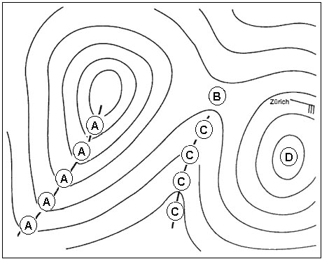
Refer to figure .when an aircraft is homing to for example to a vor station it means that the aircraft flies the most direct heading to reach the station important to know is that heading does not take into account the wind the lateral displacement an aircraft is experiencing due to the wind is called drift .as seen in the figure the aircraft is homing to the vor station on heading 360 however this is the heading needed to fly directly to the station without taking into account the experienced drift the direction of drift depends on the direction of the wind to correct for the drift angle a wind correction angle is needed the wind correction is always against the wind so left wind left wind correction angle right wind right wind correction angle .as general rule .when the aircraft experiences right drift meaning a wind from the left the track will be heading + drift angle.when the aircraft experiences left drift meaning a wind from the right the track will be heading – drift angle.if heading 360 is selected but the track indicates heading 010 the aircraft will not reach the station when the aircraft magnetic heading decreases meaning the heading will become less than 360 the airplane is correcting for right drift as seen as the red dotted line in the figure exemple 299 Right drift

Question 199-2 : Which one of the following disturbances is most likely to cause the greatest inaccuracy in adf bearings ?

Local thunderstorm activity
Thunderstorms can have very powerful discharges of static electricity across the electromagnetic spectrum including in low frequency lf and medium frequency mf these discharges cause the most severe errors in ndb/adf .a static discharge in a cumulonimbus cloud cb can be heard as a loud crackle on the audio and the needle will move rapidly to the source of the cb if there are several active thunderstorms in the area the needle might point to them for a longer period exemple 303 Local thunderstorm activity

Question 199-3 : Of what use if any is a military tacan station to civil aviation ?

It can provide dme range
Learning objective 062 02 04 01 08 state that military uhf tactical air navigation aid tacan stations may be used for dme information .tacans are military radio aids that can be used by military aircraft with the correct receiver fitted they can give distance and radial information similar to a vor/dme installation can civilian aircraft are limited and can use the distance function the same as using a dme but cannot receive the radial information exemple 307 It can provide dme range.

Question 199-4 : Which of the following is an ils localiser frequency ?

109 15 mhz
The ils localizer frequency appear in the very high frequency vhf ranging between 108 10 and 111 95 mhz only the frequencies that start with the odd decimals are used specifically as localizer frequencies for example 108 10 108 15 108 30 108 35 etc .the only correct answer for this question can be the frequency between 108 10 and 111 95 mhz which has an odd decimal number so in this case 109 15 mhz . continues on next page .. . . frequency name. frequency. application. . . very low frequency vlf . 3 30 khz. nil. . . low frequency lf . 30 300 khz. ndb/adf. . . medium frequency mf . 300 3000 khz. ndb/adf long range communications. . . high frequency hf . 3 30 mhz. long range communications. . . very high frequency vhf . 30 300 mhz. short range communication vdf vor ils localizer marker beacons. . . ultra high frequency uhf . 300 3000 mhz. ils glide path dme ssr satelite communications gnss long range radars. . . super high frequency shf . 3 30 ghz. radalt awr mls short range radars. . . extremely high frequency ehf . 30 300 ghz. nil exemple 311 109.15 mhz

Question 199-5 : An ndb transmits a signal pattern in the horizontal plane which is ?

Omnidirectional

Non directional beacon ndb .the ndb is a ground based transmitter operating in the mf or lf band widths and situated in a ground station that broadcasts signals in all directions omnidirectional which are received by the adf or automatic direction finder a standard instrument onboard aircraft exemple 315 Omnidirectional

Question 199-6 : A vor and an ndb are located in the same position both the vor and the adf readings are displayed on the rmi the aircraft is tracking away from the beacons along the 090 radial the magnetic variation is changing rapidly which of the following is correct ?

The direction of the adf pointer will change the direction of the vor pointer will not change
There are significant differences in adf and vor systems . an automatic direction finding adf system uses a groundbased non directional beacon ndb that broadcasts an omnidirectional am signal that can be picked up by the aircraft’s adf system this way the ndb system can be located on the ground adf is a short/medium range navigation system operating between 190 and 1750 khz . a vhf omnidrectional range vor system works on the principle of phase difference in the two radio signals transmitted from the vor station one signal is omnidirectional while the other signal is a 360degrees variable radials vor operates in the range of 108 and 117 95 mhz .the big difference between adf and vor systems is the magnetic variation when ndb/adf is in use the magnetic variation will change at the aircraft instruments while using vor systems the magnetic variation will always happen at the station itself .when flying away from the station the radial at which the aircraft is flying will always be the same indication since it’s not changing at the aircraft the needle of the adf will show a variation magnetic variation as the aircraft moves away from the station exemple 319 The direction of the adf pointer will change, the direction of the vor pointer will not change.

Question 199-7 : Which of the following is correct regarding false beams on a glide path ?

False beams will only be found above the correct glide path
Refer to figure .the glidepath works similar to the localizer except the glidepath operates in the ultra high frequency uhf instead of the very high frequency vhf band as seen in the figure there are 2 lobes on the glidepath one lobe at 90 hz which indicates that the aircraft is above the glidepath and one lobe at 150 hz which indicates that the aircraft is below the glidepath the centre is typically set to a 3° glidepath .despite the accuracy of the system there can be some sidelobes created these sidelobes are not as powerful as the main ones but can provide multiple false glideslopes above the main lobe false glideslopes will never be encountered when approaching the glidepath from below an indication of a false glidepath could be seen in the rate of descent if the rate of descent required is higher than stated in the charts for example 1500 fpm instead of 500 fpm the aircraft will be on a false glidepath the false glidepath is usually about twice the normal angle and the weaker side lobes may indicate up to 4 times the glide angle exemple 323 False beams will only be found above the correct glide path.

Question 199-8 : Which one of the following correctly lists the major ground based components of a microwave landing system mls ?

Separate azimuth and elevation transmitters dme facility
The microwave landing system mls is a precision radio guidance system that is used to guide the aircraft towards the runway the principle works the same as an instrument landing system ils it gives horizontal and vertical guidance to land in all weather conditions .the system consists of several different parts .. approach azimuth. back azimuth. elevation guidance. range guidance dmep . data communications exemple 327 Separate azimuth and elevation transmitters, dme facility

Question 199-9 : One of uses of the vdf service is providing aircraft with ?

Homing
The vhf direction finder vdf is a means of providing a pilot with the direction to fly towards a ground station a bearing the bearing can be used to ‘home’ towards the ground station or it can be used to identify the exact position of the aircraft by multiple bearings from other vdf facilities .a pilot may request a vdf bearing using the appropriate phrase of q code .the following q codes can be used .qdm = magnetic bearing to the station.qdr = magnetic bearing from the station.quj = true bearing to the station.qte = true bearing from the station exemple 331 Homing.

Question 199-10 : To provide a pilot with the position of the aircraft in the absence of radar atc must have at its disposal at least… ?

Two vdfs at different locations able to take bearings simultaneously on the transmitted frequency
Vdf vhf direction finding is a method of measuring the direction from which a vhf signal came it has been used for many decades now by ground stations and is particularly useful as the transmitting aircraft only needs a standard vhf radio to ask for a vdf bearing from a suitably equipped atsu this can give them ..qdm magnetic bearing from the aircraft to the station .qdr magnetic bearing from the station to the aircraft .quj true bearing from the aircraft to the station .qte true bearing from the station to the aircraft ..with 2 suitable bearings from different ground stations there is enough information to calculate a location of an aircraft whether that is the pilot drawing on a chart and finding the location or the controllers on the ground using their system more bearings provide a more accurate location and the best bearings are where the lines cross at close to 90º this means that the two vdf ground stations are required that are not too close together .these days a computer system with access to multiple vdf aerials can perform a process called auto triangulation to find the exact location that a particular transmission was broadcast from this is most notably used by distress and diversion 121 5 mhz exemple 335 Two vdfs at different locations, able to take bearings simultaneously on the transmitted frequency.

Question 199-11 : Allocated frequencies for ndb are ?

190 khz to 1750 khz
An ndb or non directional beacon is a ground based low frequency radio transmitter used as an instrument approach for airports and offshore platforms the ndb transmits an omni directional signal that is received by the adf or automatic direction finder a standard instrument onboard aircraft the pilot uses the adf to determine the direction to the ndb relative to the aircraft .to navigate using the adf the pilot enters the frequency of the ndb and the compass card or arrow on the adf will indicate the heading to the station the signal is transmitted on an uninterrupted 24/7 basis an audible morse code call sign of one or more letters or numbers is used to identify the ndb being received ndb’s used for aviation are standardized by icao the international civil aviation organization annex 10 which specifies that ndb be operated on a frequency between 190 to 1800 khz .the main components of an ndb ground station are the beacon transmitter antenna tuning unit and antenna typically ndbs have output power from 25 to 125 watts for reception up to approx 100 nm higher power systems from 500 to 1000 watts are used for longer range applications range depends on a number of factors such as output power antenna ground conductivity frequency site conditions latitude and the condition of the adf receiver exemple 339 190 khz to 1750 khz.

Question 199-12 : Locators are ?

Lf/mf ndbs used as an aid for final approach
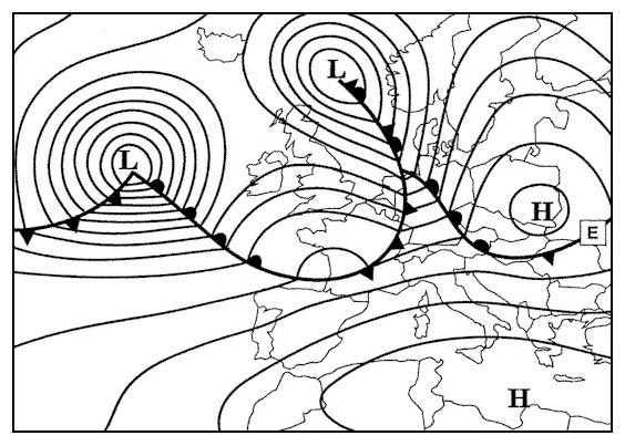
Locator beacons are low powered ndbs used for terminal procedures and approaches with useful ranges of between 10 and 25 nm ndbs are non directional beacons that transmit a simple carrier wave with a modulation to overlay the morse code identifier the adf automatic direction finder is the equipment in the cockpit which points a needle directly towards the ndb in question by finding out which direction the radio wave arrived from .ndbs operate between 190 and 1750 khz which spans both the lf low frequency 30 300 khz and mf medium frequency 300 3000 khz frequency bands exemple 343 Lf/mf ndbs used as an aid for final approach.

Question 199-13 : According to icao annex 10 a locator has a range of ?

10 to 25 nm
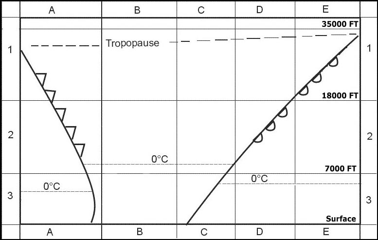
Refer to figure .the outer marker which normally identifies the final approach fix faf is often combined with a non directional beacon ndb which together creates the locator outer marker lom the lom is used as a navigational aid for the ils so that aircraft will be alerted when overflying it and offer the possibility to fly to it directly .as seen in the figure icao annex 10 states the following exemple 347 10 to 25 nm

Question 199-14 : Tvor is a ?

Vor with a limited range used in the terminal area
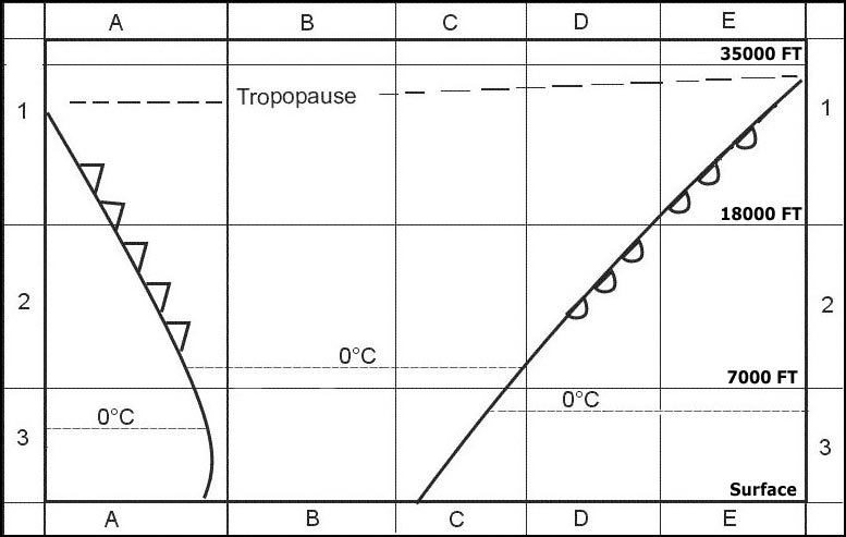
Vor applications.vors are used for en route navigation usually to define airway centrelines the overall required accuracy of the displayed information is ± 5° when european airways were first plotted out a lower accuracy of ± 7 5° was assumed to keep an aircraft within the confines of an airway 10nm maximum distance between the beacons was calculated to be 80nm .vor can be classified as follow .a terminal vor tvor is a low power beacon used as part of an airfield approach tvors share the lower frequencies with ils . .a broadcast vor is usually a terminal aid with a voice broadcast giving out the airfield weather atis superimposed on the carrier wave .a test vor vot is a very low power beacon sited at airfields it puts out a constant phase difference of zero in all directions this allows aircraft to test the accuracy of their equipment on the ground the vor test function is selected with a course of 000° set the course deviation indicator should centre with from indicated the rmi should indicate 180° qdm the beacon ident for a test vor is a series of dots .pay attention do not confuse a tvor with a test vor .question 623419 . .max range at which you will receive a signal/indication will depend on trasmitter power altitude receiver sensitivity atmospheric conditions and various other intangible factors .the max theoretical range in nautical miles was always worked out thus . .r = 1 23 h3 + h4 .where .h3 = altitude/ height of the reciver in ft . .h4 = elevation of the ground facility in ft.111 nm = 1 23 ft + 169 ft . .111 nm = 1 23 ft + 13 ft . . ft + 13 = 111 ÷ 1 23 . . ft + 13 = 90 4 . . ft = 90 4 – 13 . . ft = 77 24 . . = 77 242 . . = 5967 = fl60 exemple 351 Vor with a limited range used in the terminal area.

Question 199-15 : On an rmi the front end of a vor pointer indicates the ?

Radial plus 180°
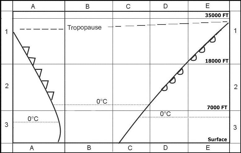
Refer to figure .heading the direction in which the longitudinal axis of an aircraft is pointed usually expressed in degrees from north true magnetic compass or grid .track the projection on the earth’s surface of the path of an aircraft the direction of which path at any point is usually expressed in degrees from north true magnetic or grid .radial a magnetic bearing extending from a vor/vortac/tacan .bearing the horizontal direction to or from any point usually measured clockwise from true north magnetic north or some other reference point through 360 degrees .heading vs radial.the radial gives the relative position of an aircraft to e g a vor .there is no mathematical relation between the radial and the heading or track of an aircraft i e one cannot be derived from the other .remember the vor needle indicates where the aircraft is radially with respect to the staion the arrow head indicates the qdm for the vor bearing to the vor station while the ther end shows the qdr or vor radial on which the aircraft is positioned at that moment exemple 355 Radial plus 180°.

Question 199-16 : Which statement about the interrogation by the dme interrogator is correct ?

The interrogation does not start before pulse pairs of the tuned dme station are received
Tuning the dme interrogator in the aircraft starts the transmission of pulse pairs in search mode no information is received by the interrogator at this point when the pulse pairs are received by the transponder at the ground station it adjusts the frequency by a pre determined + or 63 mhz which are transmitted back to and received by the interrogator it is only now that we have a closed loop between the interrogator and the transponder think about it logically you cannot interrogate something unless you have first established communications with that something .therefore simply transmitting in search mode cannot be considered to be an interrogation the loop must be closed first to establish there is a transponder present to interrogate exemple 359 The interrogation does not start before pulse-pairs of the tuned dme-station are received.

Question 199-17 : An aeroplane is on approach with nav 1 tuned to the ils frequency and nav 2 tuned to the vor frequency which also provides an approach to the same runway when the cdi of nav 1 is at exactly full scale deflection the nav 2 cdi will show approximately ?

Quarter scale deflection

Refer to figure .vors and ilss often use the same displays in the cockpit with the lateral display of the cdi course deviation indicator useful for displaying vor or localiser deviation and the vertical display showing glide path deviation they do not however have the same level of accuracy as a localiser has to be much more accurate than a vor .therefore on a standard 5 dot cdi vors have a deviation indicated by 2 degrees per dot so full scale deflection is 10º deviation from the selected bearing .ils localisers loc on the other hand have just 0 5 degrees per dot deviation so full scale deflection is 2 5º deviation from the localiser centreline .therefore in this scenario where we are on exactly full scale loc deflection we are 2 5º off the correct inbound course which is a quarter of the scale deflection on the vor display exemple 363 Quarter scale deflection.

Question 199-18 : Mls is primarily being installed at airports where ?

Ils encounters difficulties because of surrounding buildings and/or the terrain or interference from local music stations
The microwave landing system mls was designed to replace ils with an advanced precision approach system that would overcome the disadvantages of ils and also provide greater flexibility to its users .however there are few mls installations in use at present and they are likely to co exist with ils for a long time mls is a precision approach and landing system that provides position information and various ground to air data the position information is provided in a wide coverage sector and is determined by an azimuth angle measurement an elevation measurement and a range measurement .mls has the ability to interrupt the transmitted signal to avoid reflection by stationary objects such as obstructions in the appropach path which makes the system less sensitive to geographic location and obstacles this and the relatively low cost of the system are its main advantages .subsidiary advantages are the ability of mls equipped aircraft to fly approach paths other than straight in and the single frequency used avoiding the requirement for frequency pairing exemple 367 Ils encounters difficulties because of surrounding buildings and/or the terrain or interference from local music stations.

Question 199-19 : Concerning adf and ndb ?

Ndb is a ground equipment and adf is an airborne equipment
Ndbs are non directional beacons that transmit a simple carrier wave with a modulation to overlay the morse code identifier they are a ground station consisting of just one aerial for transmission .the adf automatic direction finder is the equipment in the cockpit which measures the direction from which the ndb carrier wave signal came and points a needle directly towards the ndb in question on one of the pilot's instruments .ndbs operate between 190 and 1750 khz which spans both the lf low frequency 30 300 khz and mf medium frequency 300 3000 khz frequency bands exemple 371 Ndb is a ground equipment, and adf is an airborne equipment.

Question 199-20 : The adf indication in the cockpit is a ?

Relative bearing on a fixed card indicator

Refer to figure . the adf indication on a fixed card inside the cockpit is a rbi relative bearing indicator . the rbi is measured in clockwise direction from the nose of the aircraft exemple 375 Relative bearing on a fixed card indicator

Question 199-21 : Night effect in an adf may cause ?

Fluctuating indications of the needle on the rmi
By day the d region absorbs signals in the lf and mf bands at night the d region disappears allowing sky wave contamination of the surface wave being used .the reason why this arises is because the phase interference of the sky wave with the surface wave because of the different paths and the induction of currents in the horizontal elements of the loop aerial .the effect is manifest by fading of the audio signal and the rmi needle fluctuating is worst around dawn and dusk when the ionosphere is in transition exemple 379 Fluctuating indications of the needle on the rmi.

Question 199-22 : Which statement is correct with respect to the different types of vor ?

A tvor has a limited range
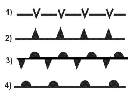
Vor applications.vors are used for en route navigation usually to define airway centrelines .the overall required accuracy of the displayed information is ± 5° .when european airways were first plotted out a lower accuracy of ± 7 5° was assumed .to keep an aircraft within the confines of an airway 10nm maximum distance between the beacons was calculated to be 80nm .vor can be classified as follow .a terminal vor tvor is a low power beacon used as part of an airfield approach tvors share the lower frequencies with ils .a broadcast vor is usually a terminal aid with a voice broadcast giving out the airfield weather atis superimposed on the carrier wave .a test vor vot is a very low power beacon sited at airfields .it puts out a constant phase difference of zero in all directions this allows aircraft to test the accuracy of their equipment on the ground .the vor test function is selected with a course of 000° set .the course deviation indicator should centre with from indicated the rmi should indicate 180° qdm the beacon ident for a test vor is a series of dots exemple 383 A tvor has a limited range.

Question 199-23 : On an ils approach when flying overhead the middle marker the colour of the flashing light will be ?

Amber
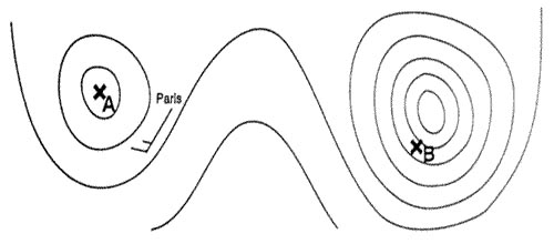
Refer to figure .there are three types of markers installed as part of a instrument landing system ils .outer marker om .this marker normally indicates the final approach fix faf it is located between 4 and 7 nm from the runway threshold on the same course as the localizer when passing the outer marker the pilot receives an audio tone in continues series of 400 hz accompanied with a flashing blue light in a continuous series of 2 second dashes .middle marker mm .this marker normally indicates the cat i missed approach point and it is positioned between 0 5 and 0 8 nm from the runway threshold when passing the middle marker the pilot receives an audio tone in continues series at 1300 hz accompanied with a flashing amber light in an alternating dots and dashes sequence .inner marker im .this marker normally indicates the passing of the runway threshold when passing the inner marker the pilot receives an audio tone in continues series of 3000 hz accompanied with a flashing white light in a dots sequence exemple 387 Amber.

Question 199-24 : On an ils approach when flying overhead the inner marker if available the colour of the flashing light will be ?

White
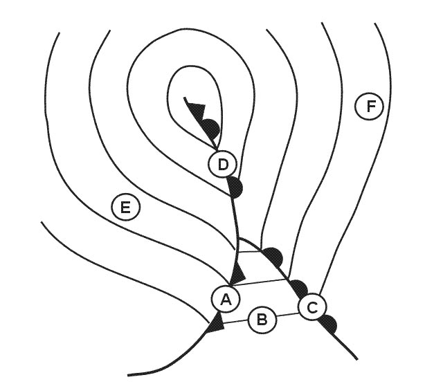
Refer to figure .there are three types of markers installed as part of a instrument landing system ils .outer marker om .this marker normally indicates the final approach fix faf it is located between 4 and 7 nm from the runway threshold on the same course as the localizer when passing the outer marker the pilot receives an audio tone in continues series of 400 hz accompanied with a flashing blue light in a continuous series of 2 second dashes .middle marker mm .this marker normally indicates the cat i missed approach point and it is positioned between 0 5 and 0 8 nm from the runway threshold when passing the middle marker the pilot receives an audio tone in continues series at 1300 hz accompanied with a flashing amber light in an alternating dots and dashes sequence .inner marker im .this marker normally indicates the passing of the runway threshold when passing the inner marker the pilot receives an audio tone in continues series of 3000 hz accompanied with a flashing white light in a dots sequence exemple 391 White.

Question 199-25 : On final on an ils approach you are flying overhead the outer marker you can expect to be at ?

4 nm from the threshold
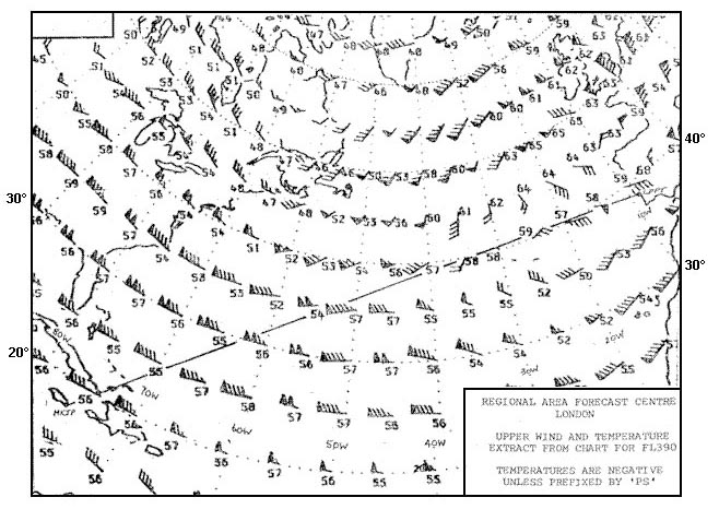
There are three types of markers installed as part of a instrument landing system ils .outer marker om .this marker normally indicates the final approach fix faf .it is located between 4 and 7 nm from the runway threshold on the same course as the localizer when passing the outer marker the pilot receives an audio tone in continues series of 400 hz accompanied with a flashing blue light in a continuous series of 2 second dashes .middle marker mm .this marker normally indicates the cat i missed approach point and it is positioned between 0 5 and 0 8 nm from the runway threshold when passing the middle marker the pilot receives an audio tone in continues series at 1300 hz accompanied with a flashing amber light in an alternating dots and dashes sequence .inner marker im .this marker normally indicates the passing of the runway threshold when passing the inner marker the pilot receives an audio tone in continues series of 3000 hz accompanied with a flashing white light in a dots sequence exemple 395 4 nm from the threshold.

Question 199-26 : The uhf band is the assigned frequency band of the ?

Ils glide path transmitter

Refer to figure .as seen in the figure ultra high frequency uhf is along with several others assigned to the ils glide path transmitter exemple 399 Ils glide path transmitter.

Question 199-27 : Ils transmitters use the ?

Uhf and vhf bands
Ils main component are .localizer .the localizer loc ground antenna array is located on the extended centerline of the instrument runway of an airport remote enough from the opposite approach end of the runway to prevent it from being a collision hazard .this unit radiates a field pattern which develops a course down the centerline of the runway toward the middle markers mms and outer markers oms and a similar course along the runway centerline in the opposite direction .these are called the front and back courses respectively .the localizer provides course guidance transmitted at 108 1 to 111 95 mhz odd tenths only throughout the descent path to the runway threshold from a distance of 18 nm from the antenna to an altitude of 4 500 feet above the elevation of the antenna site .the localizer course is very narrow normally 5° this results in high needle sensitivity .with this course width a full scale deflection shows when the aircraft is 2 5° to either side of the centerline .this sensitivity permits accurate orientation to the landing runway .with no more than one quarter scale deflection maintained the aircraft will be aligned with the runway .glide slope .glide slope gs describes the systems that generate receive and indicate the ground facility radiation pattern .the glide path is the straight sloped line the aircraft should fly in its descent from where the glide slope intersects the altitude used for approaching the faf to the runway touchdown zone .the glide slope equipment is housed in a building approximately 750 to 1 250 feet down the runway from the approach end of the runway and between 400 and 600 feet to one side of the centerline .the course projected by the glide slope equipment is essentially the same as would be generated by a localizer operating on its side .the glide slope projection angle is normally adjusted to 2 5° to 3 5° above horizontal so it intersects the mm at about 200 feet and the om at about 1 400 feet above the runway elevation .at locations where standard minimum obstruction clearance cannot be obtained with the normal maximum glide slope angle the glide slope equipment is displaced farther from the approach end of the runway if the length of the runway permits or the glideslope angle may be increased up to 4° .marker beacons .all markers operate on 75 mhz vhf thus no frequency selections are necessary for the pilot and radiate a fan shaped field pattern giving to the pilot an indication of range from the threshold .the purpose of the markers is to provide range information while on the approach .they transmit an almost vertical beam almost all installations are equipped with an outer marker and a middle marker .category 2 or 3 ils may be equipped with an inner marker as well .audio and visual signals in the cockpit will indicate when the aircraft is passing overhead .in many installations marker beacons are being replaced or supplemented by the use of a dme associated with the ils exemple 403 Uhf and vhf bands.

Question 199-28 : The localiser transmitters operate in a frequency band between ?

108 mhz and 111 975 mhz

Refer to figure .the ils localizer appears in the very high frequency vhf ranging between 108 10 and 111 975 mh exemple 407 108 mhz and 111.975 mhz.

Question 199-29 : 108 35 mhz can only be ?

An ils frequency
The ils localizer frequency appear in the very high frequency vhf ranging between 108 10 and 111 95 mhz .the vor appears in the vhf band typically between 108 00 and 117 95 mhz .. the range between 108 00 and 111 95 mhz is split between the ils and terminal vors so that an even number in the first decimal place is a vor and an odd number is an ils therefore 108 35 mhz is an ils frequency exemple 411 An ils frequency.

Question 199-30 : Which statement about adfs is correct ?

Adfs can receive and take bearings on any broadcasting station transmitting within the frequency band 190 – 1750 khz

Refer to figure .as seen in the figure the adf operates in both the low frequency lf and medium frequency mf band specifically the adf is able to receive bearings between 190 and 1750 khz exemple 415 Adfs can receive and take bearings on any broadcasting station transmitting within the frequency band 190 – 1750 khz.

Question 199-31 : What is the reason that a dme station can generally respond to a maximum of 100 aircraft ?

The number of reply pulse pairs per second that a dme transponder can transmit is limited to a certain maximum value
The response function of a dme transponder involves a continuous process that operates at a transmission rate of 2 700 pairs of pulses per second ppps once the transponder starts receiving pulses at this rate it reaches a state of saturation leading to an automatic reduction in its receiver gain this adjustment has the consequence of filtering out transmissions from aircraft whose interrogation pulses are relatively weaker .in practical terms this translates to approximately 100 aircraft concurrently utilizing the dme system .the fortunate group of 100 consists of those aircraft emitting the most potent interrogation signals rather than necessarily being the closest ones when the ground based dme station undergoes saturation it exclusively acknowledges the 100 most robust signals exemple 419 The number of reply pulse pairs per second that a dme-transponder can transmit is limited to a certain maximum value.

Question 199-32 : If the number of pulse pairs received by the dme transponder exceeds the maximum number possible which aircraft will always be denied a dme range first ?

The aircraft from which the weakest pulse pairs are received
Distance measuring equipment dme is a type of secondary radar system that provides slant range using the pulse technique the aircraft’s interrogator transmits a stream of pseudo random omni directional pulse pairs on the carrier frequency of the ground transponder the ground transponder then receives these waits for 50 microseconds and repeats those pulse pairs outwards at a frequency 63 mhz above the interrogation frequency the airborne system identifies its own unique stream of pulse pairs and measures the time of arrival electronically between the start of the interrogation and the reception of the ground transponder's replies given the time delay minus known times such as the 50 microseconds the distance between the aircraft and the dme ground station can be quite precisely calculated as there is only one interrogation frequency and one reply frequency for each dme ground station they can only service a certain number of pulses per second and it ends up meaning that the dme becomes saturated with around 100 aircraft using it and it will then prioritise the pulses with the strongest signal the aircraft that are closer to the ground station and the ones with the stronger transmitting power will therefore be higher priority to be serviced by the dme ground station exemple 423 The aircraft from which the weakest pulse pairs are received.

Question 199-33 : If during an ils approach after having been established the pilot deviates by more than half scale deflection on the localizer ?

An immediate missed approach should be executed because obstacle clearance may no longer be guaranteed

The instrument landing system ils is a system that provides the guidance of an aircraft towards the final approach the system provides the aircraft with specific horizontal localizer and vertical glideslope guidance with determining the limits of these guidances there will be a specific area determined which is clear of obstacles .an aircraft that has turned onto the inbound heading and is within 2 5 degrees of the localizer course which means half a scale of deflection on the ils instrument in the cockpit is established on the final approach course .half a scale of deflection are the boundaries of the ils and once going further than half a scale deflection there might not be enough obstacle clearance and a go around should be initiated exemple 427 An immediate missed approach should be executed because obstacle clearance may no longer be guaranteed.

Question 199-34 : Fm broadcast stations transmitting just below 108 mhz are ?

Likely to cause interference to ils receivers not equipped with an immunity filter
The instrument landing system ils localizer operates between 108 and 111 975 mhz .fm broadcasting is a method of radio broadcasting using frequency modulation fm fm broadcasting uses the same frequency range as the ils the very high frequency vhf range .the receiving unit of the ils on the aircraft will receive the radio waves that the ils is sending out apart from the correct radiowaves the receiving unit can also receive the broadcasted fm radio signals which will interfere the ils indication and might give false data adding onboard electro magnetic interference emi filters immunity filters or special layout techniques can help in bypassing the interference received from the fm broadcasts exemple 431 Likely to cause interference to ils receivers not equipped with an immunity filter.

Question 199-35 : The definition of the term qdr is… ?

The magnetic bearing from the station

Refer to figure . .as seen in the figure there is a system of abbreviations that indicates what kind of bearing is described .qdm = magnetic bearing to the station . .qdr = magnetic bearing from the station . .quj = true bearing to the station . .qte = true bearing from the station exemple 435 The magnetic bearing from the station

Question 199-36 : Reflections from large objects within the ils coverage area may cause ?

Multi path interference
An instrument landing system ils consists of a localizer and a glide path this system needs to be installed in possibly uneven terrain uneven terrain might interfere with the ils .multipath interference to ils depends on the type of antenna used and any large reflecting objects in the area like mountains moving objects can degrade the directional signals that the interference on the system will be too high to be tolerated exemple 439 Multi-path interference.

Question 199-37 : The accuracy the pilot has to fly the required bearing in order to be considered established during an adf approach according to icao doc 8168 as within plus or minus ?

A non directional beacon ndb is a ground based low frequency radio transmitter used as an instrument approach for airports and offshore platforms .the ndb transmits an omni directional signal that is received by the adf or automatic direction finder a standard instrument onboard aircraft the pilot uses the adf to determine the direction to the ndb relative to the aircraft .a non precision approach is an instrument approach and landing which utilises lateral guidance but does not utilise vertical guidance icao annex 6 .non precision approaches which are pilot interpreted make use of ground beacons and aircraft equipment such as vhf omnidirectional radio range vor non directional beacon and the llz element of an ils system often in combination with distance measuring equipment dme for range .lateral guidance is provided by a display of either bearing to/from a radio beacon on the approach track or at the airfield or in the case of an llz only approach by display of the relative position of the llz track on the aircraft ils instruments and vertical guidance is based on the range from the airfield as indicated by a dme at the airfield or on track or by timing based upon passage overhead radio beacons on the track described by the designated procedure .remember in terms of lateral errors permitted flying an ndb npa you must maintain a qdm/qdr that is ± 5° of the designated approach exemple 443 5°

Question 199-38 : With respect to the monitoring system of a vor which statement is correct ?

Failure of the vor station to stay within the required limits can cause the removal of identification and navigation components from the carrier or radiation to cease
All vor beacons are monitored by an automatic site monitor the monitor will warn the control point and remove either the identification and the navigational signals or switch off the beacon in the event of the following . bearing information change exceeding 1°. a reduction of more than 15% in signal strength. a failure of the monitor exemple 447 Failure of the vor station to stay within the required limits can cause the removal of identification and navigation components from the carrier or radiation to cease.

Question 199-39 : Which frequency can be used by a terminal vor ?

108 20 mhz
Refer to figure .as seen in the table the vor vhf omnidirectional range uses the very high frequency vhf band to transmit it’s electromagnetic waves terminal vor uses specific frequencies vor uses even decimals and even decimals plus 0 05 mhz for example 108 0 108 005 108 20 108 25 108 40 108 45 etc exemple 451 108.20 mhz.

Question 199-40 : A pilot is tracking inbound to a vor on a designated radial using the hsi the vor ground station is located in an area with varying terrain and man made obstructions the pilot notices that the cdi is fluctuating slightly even though he/she is constantly and accurately tracking inbound to the ?

Scalloping
Site error is caused by uneven terrain for example hills trees buildings and long grass near the transmitter although the propagation has left the vor with ±1° accuracy propagation error still exists propagation error is caused by the terrain and distance at a certain range from the vor so called ‘bends’ or ‘scalloping’ can occur vor scalloping is described as an imperfection or deviation in the received vor signal scalloping causes the signal to bend as a result of reflections from buildings and terrain scalloping also causes the course deviation indicator cdi to slowly or rapidly shift from side to side scalloping has a negative effect on the accuracy of the navigation aids used exemple 455 Scalloping


~

Exclusive rights reserved. Reproduction prohibited under penalty of prosecution.

7919 Free Training Exam