A free Premium account on the FCL.055 website! Read here
Sign up to unlock all our services and 15164 corrected and explained questions.
Question 212-1 : The difference between a cvor and a dvor indicates that dvor is more accurate because ? [ Preparation civilian ]
It is less sensitive to errors generated by the environment buildings hills
Question 212-2 : The pulse p2 of an interrogation in ac mode has the function ?
Of avoiding responses of aircraft located in the direction of the side lobes of the antenna of the interrogator.
Of avoiding garbling if two aircraft in the same direction from the interrogator and at a distance of less than 1.7 nm. of determining the interrogation mode. of avoiding 'fruiting' is an aircraft is interrogated by more than one secondary radar.
Question 212-3 : A transponder receives a p2 pulse which is larger than that of the p1 and p3 ?
Transponder transmissions will be suppressed for a short time.
The transmitting station is out of order. transponder transmission will be increased. the pulses p1 and p3 will be strengthened to reach the same level.
Question 212-4 : The integrity of a vor system is improved by ?
An automatic ground monitoring system.
Test vor (vot) beacons on airports areas. at least two independent airborne vor receivers. one autonomous airborne monitoring receiver.
Question 212-5 : The controller of a vdf ground station pass you the following message 'your true bearing is 256° class alpha'this is a ?
Qte accurate to a range within ± 2°.
Bravo nice and very interesting question from the easa there's nothing more to say than that 2559 qte the true bearing from the stationquj the true bearing to the stationqdr the magnetic bearing from the stationqdm the magnetic bearing to the stationvdf information is divided into the following classes according to icao annex 10 class a accurate to a range within ± 2° class b accurate to a range within ± 5° class c accurate to a range within ± 10° class d accurate to less than class cQdr accurate to a range within ± 2°. quj accurate to a range within ± 3°. qte accurate to a range within ± 5°.
Question 212-6 : Which of the following is the correct class and accuracy for a vdf direction finder ?
Class a ± 2°.
2604they should take a break at the easa officesvdf information is divided into the following classes according to icao annex 10 class a accurate to a range within ± 2° class b accurate to a range within ± 5° class c accurate to a range within ± 10° class d accurate to less than class cClass a ± 10°. class c ± 2°. class d ± 5°.
Question 212-7 : An aircraft is inbound to vor x on the 073° radial and experiences a drift of 12°l a position report is required when crossing the 133° radial from vor y if the aircraft is on track the rmi indications at the reporting point would be ?
Heading 265° x pointer 253° y pointer 313°.
Heading 085°, x pointer 073°, y pointer 133°. heading 265°, x pointer 073°, y pointer 313°. heading 085°, x pointer 253°, y pointer 133°.
Question 212-8 : In the case where a dme station is subjected to more than 100 interrogations which aircraft will no longer receive a response from the dme ?
Those who have the lowest transmission.
A typical dme transponder can provide distance information to 100 aircraft at a time above this limit the transponder avoids overload by limiting the gain of the receiver replies to weaker more distant interrogations are ignored to lower the transponder loaddme can be used by 300 users at one time the technical term of the dme station when its overloaded and cannot accept more than 100 aircraft is called 'station or beacon saturation'The closest. the most distant. those over 200 nm.
Question 212-9 : In the case where a dme station is subjected to more than 100 interrogations which aircraft s will receive a dme response ?
Those who have the most powerful transmission.
A typical dme transponder can provide distance information to 100 aircraft at a time above this limit the transponder avoids overload by limiting the gain of the receiver replies to weaker more distant interrogations are ignored to lower the transponder loaddme can be used by 300 users at one time the technical term of the dme station when its overloaded and cannot accept more than 100 aircraft is called 'station or beacon saturation'The closest. the most distant. those over 200 nm.
Question 212-10 : What is the reason that a dme station can generally respond to a maximum of 100 aircraft ?
The number of reply pulse pairs per second that a dme transponder can transmit is limited to a certain maximum value.
The minimum allowable accuracy of the range measurement can not be guaranteed when more than 100 aircraft use the same dme station. the memory of the dme transponder which is limited in size. the automatic tracking ground station of each dme station that has limited capacity.
Question 212-11 : Which entrance sectors should you use to enter a dme arc holding pattern ?
Sector 1 or 3.
Icao doc816 dme arc entry at the fix the aircraft shall enter the holding pattern in accordance with either the sector 1 or sector 3 entry proceduresector 2 is on the dme arc which is why it is not in the allowed sectors to enter the holding pattern at the beginning of the dme arcsector 1 procedure parallel entrysector 2 procedure offset entrysector 3 procedure direct entrySector 1 or 2. sector 1, 2 or 3. sector 2 or 3.
Question 212-12 : A direction finding station working alone should give the following as requested ?
Magnetic and true bearing to the station magnetic and true heading for the station.
Ecqb04 november 2017a direction finding station working alone should give the following as requested 1 true bearing of the aircraft 2 true heading to be steered by the aircraft with no wind to head for the station 3 magnetic bearing of the aircraft 4 magnetic heading to be steered by the aircraft with no wind to make for the stationTrue bearing to the station, magnetic and true heading for the station. true bearing to the station, true heading for the station. true bearing to the station.
Question 212-13 : In vdf service the report 'qdr 235° class c' means ?
The magnetic bearing from the station to the aircraft is 235° ± 10°.
Ecqb04 november 2017 com enhead explodegifthey should take a break at the easa officesqte the true bearing from the stationquj the true bearing to the stationqdr the magnetic bearing from the stationqdm the magnetic bearing to the stationvdf information is divided into the following classes according to icao annex 10 class a accurate to a range within ± 2° class b accurate to a range within ± 5° class c accurate to a range within ± 10° class d accurate to less than class cThe magnetic bearing from the aircraft to the station is 235° ± 10°. the true bearing from the aircraft to the station is 235 ± 10°. the magnetic bearing from the station to the aircraft is 235 ± 15°.
Question 212-14 : The sensitive area of an ils is the area vehicles or taxiing aircraft may not enter when ?
Category iiiii ils operations are in progress.
The ils critical area is an area of defined dimensions about the localizer and glide path antennas where vehicles including aircraft are excluded during all ils operationsthe critical area is protected because the presence of vehicles andor aircraft inside its boundaries will cause unacceptable disturbance to the ils signal in spacethe ils sensitive area is an area extending beyond the critical area where the parking andor movement of vehicles including aircraft is controlled to prevent the possibility of unacceptable interference to the ils signal during ils operationsthe sensitive area is protected against interference caused by large moving objects outside the critical area but still normally within the airfield boundarycritical areas must be protected to all times while ils sensitive areas should be kept clear during cat ii or cat iii operations airplane must stop taxing at the rwy cat ii or cat iii holding pointsCategory i ils operations are in progress. the ils is undergoing calibration. ils operations are in progress.
Question 212-15 : You are flying along an airway which is 10 nm wide 5 nm either side of the centreline the distance to the vordme you are using is 100 nm if you are on the airway boundary how many dots deviation will the vor needle show if one dot represents 2 degrees ?
15.
Refer to figureas seen in the figure the aircraft is on the airway boundary which is 5 nm form the intended course the cdi therefore will show a deflection to the right since the selected course will be directly inbound to the stationthe distance that dme shows 100 nm which should be the hypotenuse but for the such distance we can approximate that the distance from the airway is the sameto calculate the angle of deflection the aircraft has relative to the intended course we can use the following formulae tangent correction angle = distance off intended track distance to go = 5nm 100nm = 005tan 1 005 = 286° = 3°if one dot represents 2° then 3° will be equal to 1 dot2° 3° = 3° x 1 dot 2° = 15 dots1 60 solution • track error angle = dist off track 60 ÷ dist along track• tea = 5 nm 60 ÷ 100 nm• tea = 3°if one dot represents 2° then 3° will be equal to 15 dots4.5 3.0 6.0
Question 212-16 : If an aircraft flies along a vor radial it will follow a ?
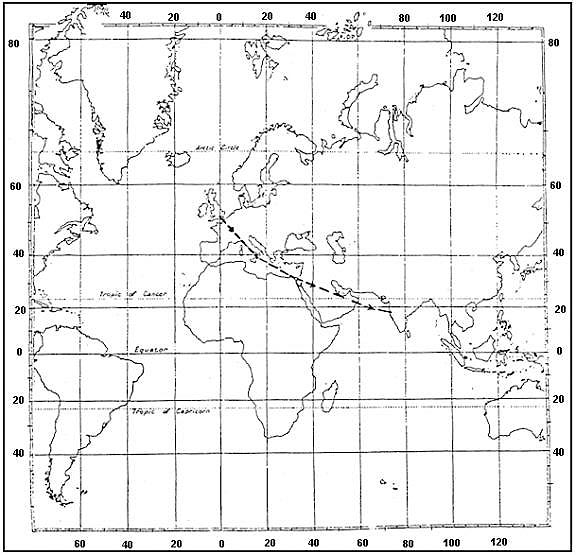
Great circle track.
A radial is a magnetic bearing extending from a vor station radials move along the compass rose in all directions radials follow the curvature of the earth just like great circle tracks as seen in the figure great circle tracks run across the earth's surface following the curvature of the earth the rhumb line is used for planning a flight on a 2d map 1462the great circle track marks the shortest distance between 2 points which is useful for navigation purposesdue to convergency usually the track changes along the great circle the equator and all the meridians longitudes that run vertically across the earth any circle that is not a great circle is called a small circle also known as parallel of latitudesRhumb line track. constant magnetic track. line of constant bearing.
Question 212-17 : Locators are 1 high powered ndbs used for en route and airways navigation 2 low powered ndbs used for airfield or runway approach 3 beacons with a usually range of 10 to 250 nm 4 beacons with a usually range of 10 to 25 nmthe combination regrouping all the correct statements is ?
2 and 4.
Ndbs used for aviation are standardised by icao annex 10 which specifies that ndbs be operated on a frequency between 190 khz and 1750 khz each ndb is identified by a one two or three letter morse code callsignnon directional beacons in are classified by power output low power rating is less than 50 watts medium from 50 w to 2000 w and high at more than 2000 w 2 there are four types of non directional beacons in the aeronautical navigation service en route ndbs used to mark airways approach ndbs localizer beacons locator beacons the last two types are used in conjunction with an instrument landing system ils locator beacons are low powered beacons with a range between 10 to 25 nm maximum1 and 4. 2 and 3. 1 and 3.
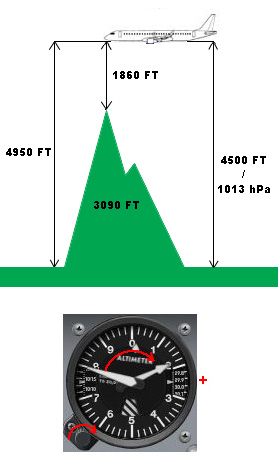
Question 212-18 : An aircraft is flying at fl 240 the dme reading uncorrected for altitude is 8 nm what is the ground distance to the beacon ?
70 nm.
Refer to figuredistance measuring equipment dme is a navigation beacon that can indicate the aircraft's position relative to the beacon aircraft send out a signal which is sent back by the dme ground equipment based on the delay of receiving the signal back the aircraft can calculate the relative distance to the dme ground equipmentas seen in the figure the aircraft is at an altitude of 24000 feet fl240 the slant range from the aircraft to the dme is 8 nmby calculating the ground distance from the aircraft to the dme station convert the following 24000 feet into nautical milesuse the following table 1 nm 6080 ft 24000 ft = 24000 ft x1 nm 6080 ft = 395 nm using the abc formulae the following can be calculated a² + b² = c²knowing that a = 395 nmb = c = 8 nmrewriting the formulae gives the following b² = c² a²b² = 8 ² 395 ²b² = 484b = 484 = 695 nm = 7 nm7.3 nm 7.5 nm 6.5 nm
Question 212-19 : What is the minimum level isa conditions that an aircraft at a range of 111 nm must fly in order to contact the tower on rt for a vdf bearing from an airport sited 169 ft above msl ?
Fl60.
A vdf facility is an abbreviation for very high frequency vhf direction findingusing this will give the pilot a determination of his current positionthe formulae used to calculate the range of these radio waves is as follows maximum theoretical range in nm = = 123 x h1 + 123 x h2h1 = the height in feet of the transmitter above mean sea level msl h2 = the height in feet of the receiver above mean sea level msl rewriting the formulae gives the following 123 x h1 = range – 123 x h2h1 = range 123 x h2 123 ²knowing that range = 111 nmh2 = 169 ftfilling in the formulae gives the following h1 = 111 nm 123 x 169 123 ² = 5966 ft = fl60Fl100 fl80 fl50
Question 212-20 : To determine the vor radial the aircraft vor receiver… ?
Measures the phase difference between the reference phase and the variable phase signals.
A vhf omni directional range vor is used as a navigation beacon for aircraft aircraft with a receiving unit will be able to determine their position relative to the vor beacon the frequency of vor's appear in the very high frequency vhf range from 10800 to 11795 mhza vor ground station sends a highly directional signal by making use of a so called phased array antenna together with this signal the vor sends a 30 hz reference signal which is equal in all direction the phase difference between the reference signal and the highly directional signal is the bearing from the vor station relative to magnetic northa vor receiver works by comparing the phase relationship between a reference signal and a variable signalUses pulse techniques. measures the time difference between sending the interrogation signal and receiving the transponder signal. measures the time difference between reception of the two signals transmitted by the ground installation.
Question 212-21 : Which of the following correctly describes the instrument landing system ils localiser radiation pattern ?
Two overlapping lobes on the same vhf carrier frequency.
Radiation pattern are 90 hz and 150 hz signals 2582distribution of the frequencies seen in the approach direction 2583if the aircraft is exactly on the glidepath on the exact runway centreline it receives a balance between modulationsTwo overlapping lobes on the same uhf carrier frequency two overlapping lobes on different radio carrier frequencies but with the same modulation a pencil beam comprising a series of smaller beams each carrying a different modulation
Question 212-22 : The middle marker of an instrument landing system ils facility is identified audibly and visually by a series of ?
Alternate dots and dashes and an amber light flashing.
Refer to figurethere are three types of markers usually installed as part of a instrument landing systemouter marker this marker normally indicates the final approach fix faf it is located between 4 and 7 nm from the runway threshold on the same course as the localizer when passing the outer marker the pilot receives an audio tone in continues series of 400 hz accompanied with a flashing blue light in a continuous series of 2 second dashesmiddle marker this marker normally indicates the cat i missed approach point and it is positioned between 05 and 08 nm from the runway threshold when passing the middle marker the pilot receives an audio tone in continues series at 1300 hz accompanied with a flashing amber light in an alternating dots and dashes sequenceinner marker this marker normally indicates the passing of the runway threshold when passing the inner marker the pilot receives an audio tone in continues series of 3000 hz accompanied with a flashing white light in a dots sequenceDashes and an amber light flashing two dashes per second and a blue light flashing dots and a white light flashing
Question 212-23 : The mls frequencies and available channels are ?
In the shf band 300 khz frequency separation giving 200 available channels.
The microwave landing system mls was designed to replace ils with an advanced precision approach system that would overcome the disadvantages of ils and also provide greater flexibility to its users however there are few mls installations in use at present and they are likely to co exist with ils for a long time mls is a precision approach and landing system that provides position information and various ground to air data the position information is provided in a wide coverage sector and is determined by an azimuth angle measurement an elevation measurement and a range measurementthe microwave landing system mls has the following features there are 200 channels available worldwide the azimuth coverage is at least ± 40° of the runway on course line qdm and glideslopes from 9° to 20° can be selected the usable range is 20 30 nm from the mls site 20nm in the uk there is no problem with back course transmissions a secondary system is provided to give overshoot and departure guidance ± 20° of runway direction up to 15° in elevation to a range of 10 nm and a height of 10000 ft it operates in the shf band 5031 5090 mhz this enables it to be sited in hilly areas without having to level the site course deviation errors bending of the localiser and glidepath caused by aircraft vehicles and buildings are no longer a problem because the mls scanning beam can be interrupted and therefore avoids the reflectionsIn the shf band for the mls elements and the vhf band for the dme, 100 available channels. in the range 5060 – 5090 mhz, 200 khz separation giving 150 available channels. in the vhf- and uhf band, 40 available channels.
Question 212-24 : An aircraft is homing to a radio beacon whilst maintaining a relative bearing of zero if the magnetic heading decreases the aircraft is experiencing ?
Right drift.
Refer to figurewhen an aircraft is homing to for example to a vor station it means that the aircraft flies the most direct heading to reach the station important to know is that heading does not take into account the wind the lateral displacement an aircraft is experiencing due to the wind is called driftas seen in the figure the aircraft is homing to the vor station on heading 360 however this is the heading needed to fly directly to the station without taking into account the experienced drift the direction of drift depends on the direction of the wind to correct for the drift angle a wind correction angle is needed the wind correction is always against the wind so left wind left wind correction angle right wind right wind correction angleas general rule when the aircraft experiences right drift meaning a wind from the left the track will be heading + drift anglewhen the aircraft experiences left drift meaning a wind from the right the track will be heading – drift angleif heading 360 is selected but the track indicates heading 010 the aircraft will not reach the station when the aircraft magnetic heading decreases meaning the heading will become less than 360 the airplane is correcting for right drift as seen as the red dotted line in the figureZero drift left drift a wind from the west
Question 212-25 : Which one of the following disturbances is most likely to cause the greatest inaccuracy in adf bearings ?
Local thunderstorm activity.
Thunderstorms can have very powerful discharges of static electricity across the electromagnetic spectrum including in low frequency lf and medium frequency mf these discharges cause the most severe errors in ndbadfa static discharge in a cumulonimbus cloud cb can be heard as a loud crackle on the audio and the needle will move rapidly to the source of the cb if there are several active thunderstorms in the area the needle might point to them for a longer periodCoastal effect precipitation interference quadrantal error
Question 212-26 : Of what use if any is a military tacan station to civil aviation ?
It can provide dme range.
Learning objective 06202040108 state that military uhf tactical air navigation aid tacan stations may be used for dme informationtacans are military radio aids that can be used by military aircraft with the correct receiver fitted they can give distance and radial information similar to a vordme installation can civilian aircraft are limited and can use the distance function the same as using a dme but cannot receive the radial informationIt is of no use to civil aviation it can provide a dme distance and magnetic bearing it can provide a magnetic bearing
Question 212-27 : Which of the following is an ils localiser frequency ?
10915 mhz.
The ils localizer frequency appear in the very high frequency vhf ranging between 10810 and 11195 mhz only the frequencies that start with the odd decimals are used specifically as localizer frequencies for example 10810 10815 10830 10835 etcthe only correct answer for this question can be the frequency between 10810 and 11195 mhz which has an odd decimal number so in this case 10915 mhz continues on next page frequency name frequency application very low frequency vlf 3 30 khz nil low frequency lf 30 300 khz ndbadf medium frequency mf 300 3000 khz ndbadf long range communications high frequency hf 3 30 mhz long range communications very high frequency vhf 30 300 mhz short range communication vdf vor ils localizer marker beacons ultra high frequency uhf 300 3000 mhz ils glide path dme ssr satelite communications gnss long range radars super high frequency shf 3 30 ghz radalt awr mls short range radars extremely high frequency ehf 30 300 ghz nil112.10 mhz 110.20 mhz 108.25 mhz
Question 212-28 : An ndb transmits a signal pattern in the horizontal plane which is ?
Omnidirectional.
Non directional beacon ndb the ndb is a ground based transmitter operating in the mf or lf band widths and situated in a ground station that broadcasts signals in all directions omnidirectional which are received by the adf or automatic direction finder a standard instrument onboard aircraftA cardioid balanced at 30 hz a beam rotating at 30 hz bi-lobal circular
Question 212-29 : A vor and an ndb are located in the same position both the vor and the adf readings are displayed on the rmi the aircraft is tracking away from the beacons along the 090 radial the magnetic variation is changing rapidly which of the following is correct ?
The direction of the adf pointer will change the direction of the vor pointer will not change.
There are significant differences in adf and vor systems an automatic direction finding adf system uses a groundbased non directional beacon ndb that broadcasts an omnidirectional am signal that can be picked up by the aircraft's adf system this way the ndb system can be located on the ground adf is a shortmedium range navigation system operating between 190 and 1750 khz a vhf omnidrectional range vor system works on the principle of phase difference in the two radio signals transmitted from the vor station one signal is omnidirectional while the other signal is a 360degrees variable radials vor operates in the range of 108 and 11795 mhzthe big difference between adf and vor systems is the magnetic variation when ndbadf is in use the magnetic variation will change at the aircraft instruments while using vor systems the magnetic variation will always happen at the station itselfwhen flying away from the station the radial at which the aircraft is flying will always be the same indication since it's not changing at the aircraft the needle of the adf will show a variation magnetic variation as the aircraft moves away from the stationThe direction of the vor pointer will change, the direction of the adf pointer will not change. neither the direction of the adf pointer nor the direction of the vor pointer will change. both the direction of the adf pointer and the direction of the vor pointer will change.
Question 212-30 : Which of the following is correct regarding false beams on a glide path ?
False beams will only be found above the correct glide path.
Refer to figurethe glidepath works similar to the localizer except the glidepath operates in the ultra high frequency uhf instead of the very high frequency vhf band as seen in the figure there are 2 lobes on the glidepath one lobe at 90 hz which indicates that the aircraft is above the glidepath and one lobe at 150 hz which indicates that the aircraft is below the glidepath the centre is typically set to a 3° glidepathdespite the accuracy of the system there can be some sidelobes created these sidelobes are not as powerful as the main ones but can provide multiple false glideslopes above the main lobe false glideslopes will never be encountered when approaching the glidepath from below an indication of a false glidepath could be seen in the rate of descent if the rate of descent required is higher than stated in the charts for example 1500 fpm instead of 500 fpm the aircraft will be on a false glidepath the false glidepath is usually about twice the normal angle and the weaker side lobes may indicate up to 4 times the glide angleFalse beams will only be found below the correct glide path. false beams will only be found more than 10 degrees to the left or to the right of the localiser centreline. false beams are only present when flying a back-beam ils approach.
Question 212-31 : Which one of the following correctly lists the major ground based components of a microwave landing system mls ?
Separate azimuth and elevation transmitters dme facility.
The microwave landing system mls is a precision radio guidance system that is used to guide the aircraft towards the runway the principle works the same as an instrument landing system ils it gives horizontal and vertical guidance to land in all weather conditionsthe system consists of several different parts approach azimuth back azimuth elevation guidance range guidance dmep data communicationsSeparate azimuth and elevation transmitters, outer and middle marker beacons combined azimuth and elevation transmitter, dme facility combined azimuth and elevation transmitter, outer and inner marker beacons
Question 212-32 : One of uses of the vdf service is providing aircraft with ?
Homing.
The vhf direction finder vdf is a means of providing a pilot with the direction to fly towards a ground station a bearing the bearing can be used to ‘home’ towards the ground station or it can be used to identify the exact position of the aircraft by multiple bearings from other vdf facilitiesa pilot may request a vdf bearing using the appropriate phrase of q codethe following q codes can be used qdm = magnetic bearing to the stationqdr = magnetic bearing from the stationquj = true bearing to the stationqte = true bearing from the stationGround speed. altitude. heading.
Question 212-33 : To provide a pilot with the position of the aircraft in the absence of radar atc must have at its disposal at least… ?
Two vdfs at different locations able to take bearings simultaneously on the transmitted frequency.
Vdf vhf direction finding is a method of measuring the direction from which a vhf signal came it has been used for many decades now by ground stations and is particularly useful as the transmitting aircraft only needs a standard vhf radio to ask for a vdf bearing from a suitably equipped atsu this can give them qdm magnetic bearing from the aircraft to the stationqdr magnetic bearing from the station to the aircraftquj true bearing from the aircraft to the stationqte true bearing from the station to the aircraftwith 2 suitable bearings from different ground stations there is enough information to calculate a location of an aircraft whether that is the pilot drawing on a chart and finding the location or the controllers on the ground using their system more bearings provide a more accurate location and the best bearings are where the lines cross at close to 90º this means that the two vdf ground stations are required that are not too close togetherthese days a computer system with access to multiple vdf aerials can perform a process called auto triangulation to find the exact location that a particular transmission was broadcast from this is most notably used by distress and diversion 1215 mhz Three vdfs at different locations able to take simultaneous bearings on different frequencies. one vdf able to take simultaneous bearings on different frequencies. two co-located vdfs, able to take bearings simultaneously on the transmitted frequency.
Question 212-34 : Allocated frequencies for ndb are ?
190 khz to 1750 khz.
An ndb or non directional beacon is a ground based low frequency radio transmitter used as an instrument approach for airports and offshore platforms the ndb transmits an omni directional signal that is received by the adf or automatic direction finder a standard instrument onboard aircraft the pilot uses the adf to determine the direction to the ndb relative to the aircraft to navigate using the adf the pilot enters the frequency of the ndb and the compass card or arrow on the adf will indicate the heading to the station the signal is transmitted on an uninterrupted 247 basisan audible morse code call sign of one or more letters or numbers is used to identify the ndb being received ndb’s used for aviation are standardized by icao the international civil aviation organization annex 10 which specifies that ndb be operated on a frequency between 190 to 1800 khz the main components of an ndb ground station are the beacon transmitter antenna tuning unit and antennatypically ndbs have output power from 25 to 125 watts for reception up to approx 100 nmhigher power systems from 500 to 1000 watts are used for longer range applications range depends on a number of factors such as output power antenna ground conductivity frequency site conditions latitude and the condition of the adf receiver1900 khz to 17500 khz. 1.90 khz to 17.50 khz. 19 hz to 17500 hz.
Question 212-35 : Locators are ?
Lfmf ndbs used as an aid for final approach.
Locator beacons are low powered ndbs used for terminal procedures and approaches with useful ranges of between 10 and 25 nm ndbs are non directional beacons that transmit a simple carrier wave with a modulation to overlay the morse code identifier the adf automatic direction finder is the equipment in the cockpit which points a needle directly towards the ndb in question by finding out which direction the radio wave arrived fromndbs operate between 190 and 1750 khz which spans both the lf low frequency 30 300 khz and mf medium frequency 300 3000 khz frequency bandsBeacons with a range of 10 to 250 nm. low powered adfs used for airfield or runway approach. high powered ndbs used for en route and airways navigation.
Question 212-36 : According to icao annex 10 a locator has a range of ?
10 to 25 nm.
Refer to figurethe outer marker which normally identifies the final approach fix faf is often combined with a non directional beacon ndb which together creates the locator outer marker lom the lom is used as a navigational aid for the ils so that aircraft will be alerted when overflying it and offer the possibility to fly to it directlyas seen in the figure icao annex 10 states the following75 to 250 nm 7.5 to 15 nm 75 to 150 nm
Question 212-37 : Tvor is a ?
Vor with a limited range used in the terminal area.
Vor applicationsvors are used for en route navigation usually to define airway centrelines the overall required accuracy of the displayed information is ± 5° when european airways were first plotted out a lower accuracy of ± 75° was assumed to keep an aircraft within the confines of an airway 10nm maximum distance between the beacons was calculated to be 80nmvor can be classified as follow a terminal vor tvor is a low power beacon used as part of an airfield approach tvors share the lower frequencies with ils a broadcast vor is usually a terminal aid with a voice broadcast giving out the airfield weather atis superimposed on the carrier wavea test vor vot is a very low power beacon sited at airfields it puts out a constant phase difference of zero in all directions this allows aircraft to test the accuracy of their equipment on the ground the vor test function is selected with a course of 000° set the course deviation indicator should centre with from indicated the rmi should indicate 180° qdm the beacon ident for a test vor is a series of dotspay attention do not confuse a tvor with a test vor question 623419 max range at which you will receive a signalindication will depend on trasmitter power altitude receiver sensitivity atmospheric conditions and various other intangible factorsthe max theoretical range in nautical miles was always worked out thus r = 123 h1 + h2 where h1 = altitude height of the reciver in ft h2 = elevation of the ground facility in ft111 nm = 123 ft + 169 ft 111 nm = 123 ft + 13 ft ft + 13 = 111 ÷ 123 ft + 13 = 904 ft = 904 – 13 ft = 7724 = 77242 = 5967 = fl60Low power dvor in the frequency range 112 mhz – 118 mhz. test vor transmitting such a signal that the reference- and variable signal are always in phase. high power vor in the frequency range 108 mhz – 112 mhz.
Question 212-38 : On an rmi the front end of a vor pointer indicates the ?
Radial plus 180°.
Refer to figureheading the direction in which the longitudinal axis of an aircraft is pointed usually expressed in degrees from north true magnetic compass or grid track the projection on the earth's surface of the path of an aircraft the direction of which path at any point is usually expressed in degrees from north true magnetic or grid radial a magnetic bearing extending from a vorvortactacanbearing the horizontal direction to or from any point usually measured clockwise from true north magnetic north or some other reference point through 360 degreesheading vs radialthe radial gives the relative position of an aircraft to eg a vorthere is no mathematical relation between the radial and the heading or track of an aircraft ie one cannot be derived from the otherremember the vor needle indicates where the aircraft is radially with respect to the staion the arrow head indicates the qdm for the vor bearing to the vor station while the ther end shows the qdr or vor radial on which the aircraft is positioned at that momentMagnetic bearing from the station. radial. relative bearing.
Question 212-39 : Which statement about the interrogation by the dme interrogator is correct ?
The interrogation does not start before pulse pairs of the tuned dme station are received.
Tuning the dme interrogator in the aircraft starts the transmission of pulse pairs in search mode no information is received by the interrogator at this point when the pulse pairs are received by the transponder at the ground station it adjusts the frequency by a pre determined + or 63 mhz which are transmitted back to and received by the interrogator it is only now that we have a closed loop between the interrogator and the transponder think about it logically you cannot interrogate something unless you have first established communications with that somethingtherefore simply transmitting in search mode cannot be considered to be an interrogation the loop must be closed first to establish there is a transponder present to interrogateThe interrogation starts directly after the correct dme-frequency has been selected on the frequency-selecting-panel by the pilot. the interrogation starts when the interrogator has been warmed up sufficiently, whether pulse-pairs are received or not. the interrogation can only take place if the echo protection circuit has been locked.
Question 212-40 : An aeroplane is on approach with nav 1 tuned to the ils frequency and nav 2 tuned to the vor frequency which also provides an approach to the same runway when the cdi of nav 1 is at exactly full scale deflection the nav 2 cdi will show approximately ?
Quarter scale deflection.
Refer to figurevors and ilss often use the same displays in the cockpit with the lateral display of the cdi course deviation indicator useful for displaying vor or localiser deviation and the vertical display showing glide path deviation they do not however have the same level of accuracy as a localiser has to be much more accurate than a vortherefore on a standard 5 dot cdi vors have a deviation indicated by 2 degrees per dot so full scale deflection is 10º deviation from the selected bearingils localisers loc on the other hand have just 05 degrees per dot deviation so full scale deflection is 25º deviation from the localiser centrelinetherefore in this scenario where we are on exactly full scale loc deflection we are 25º off the correct inbound course which is a quarter of the scale deflection on the vor displayHalf scale deflection. full scale deflection. no deflection.
Exclusive rights reserved. Reproduction prohibited under penalty of prosecution.