A free Premium account on the FCL.055 website! Read here
Sign up to unlock all our services and 15164 corrected and explained questions.
Question 217-1 : You are flying the inbound course of an ndb holding pattern in an area of local thunderstorm activity what might the adf indicate ? [ Preparation civilian ]
The needle will point towards the thunderstorm
Question 217-2 : During an ils approach with 3º glide slope you initiate a go around when the dme reads 1 nm from the threshold and decreasing you are at a height of 1 200 ft over the runway elevation and you notice that the glidepath indicator is showing no deflection and no flags as if you were correctly on the ?
The aircraft is flying within the side lobes of the glide path signal.
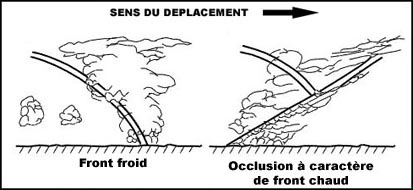
The glidepath of an ils works similar to the localizer except the glidepath operates in the ultra high frequency uhf instead of the very high frequency vhf bandas seen in the figure there are 2 lobes on the glidepathone lobe at 90 hz which indicates that the aircraft is above the glidepathand one lobe at 150 hz which indicates that the aircraft is below the glidepaththe centre is typically set to a 3° glidepaththis is not a perfect system and the glidepath can suffer from the presence of false glidepaths above the correct onethese are due to both the weak sidelobes of the original 150 hz and 90 hz lobes which are created and intensified by the reflection of the lower signals off the ground or nearby obstaclesthis is the similar to multipath interference of the localiser but is more easy to predictthese false glidepaths are reverse sensing see 2nd annex above and usually exist at odd multiples of the original glidepath and are the reason why we procedurally will intercept the glidepath from below to avoid encountering a false glidepathnote we have had updated feedback in the comments on this question but could still use more to fine tune the wording and check the other optionsThe instrument has failed and has kept the previous indication. the aircraft is flying through the opposite runway glide path the approach has a higher glide path.
Question 217-3 : You are flying across northern canada on airway nca whiskey you wish to cross check the irs computed position by taking a bearing from a nearby vor you tune into the churchill vor and find you are on the 190° radial what is the bearing to plot on a chart if the variation at the vor is 2°w and the ?
188°.
Refer to figure to cross check our position using a chart we must find the true bearing from a known position to our aircraft in this case the known position is the churchill vor and we are on radial 190° radials from vors are in magnetic so we know the magnetic bearing from the vor to the aircraft is 190° m and also that we should use the variation at the vor to calculate our true bearing an easy way to remember this is that v is for vor and also for variation so use the variation at the vor there are many ways to turn this into a true bearing one of which is the rhyme variation east magnetic least variation west magnetic besttherefore our magnetic bearing of 190° is greater than our true bearing by the amount of 2° so the true bearing to plot from the vor on the chart would be 188° t note 1 another piece of information would still be required to compute the position of the aircraft such as another vor bearing or a dme readout note 2 in canada airspace northern domestic airspace nda is the area of compass unreliability within which runways and navaids are oriented to true north however churchill vor is not included in nda airspace as they would have to specify this in the question note 3 there is another extremely similar question with radial 300° so do not get this mixed up with that one or vice versa118° 194° 298°
Question 217-4 : What criteria must be met to be considered established on an ndb approch ?
The bearing pointer must be within 5º of the required course.
A non directional beacon ndb is a ground based low frequency radio transmitter used as an instrument approach for airports and offshore platformsthe ndb transmits an omni directional signal that is received by the adf or automatic direction finder a standard instrument onboard aircraft the pilot uses the adf to determine the direction to the ndb relative to the aircraftndb's can be used to provide a non precision approach to an airport a pilot can make sure to be aligned with the correct approach path by maintaining the same qdm with the adf and can manage vertical guidance using their altimeter with a minimum descent heightaltitudein terms of lateral errors permitted flying an ndb approach you must maintain a qdmqdr that is ± 5° of the designated approach path this is also the range in which an aircraft can be considered established on the approachas the process of flying ndb approaches varies depending on the cockpit hardware this question could potentially cause some confusion let's look at each option the relative bearing must be less than 5º this is incorrect as the relative bearing direction of the adf pointer relative to the aircraft heading will vary due to the wind correction angle an aircraft could be perfectly flying an inbound course of 270º but with a 10º right wind correction so heading 280º the relative bearing would be 350º 10º left of the nose but the aircraft would be established the bearing pointer must be within 5º of the required course this is true as the bearing pointer indicates the qdm when using an rmi or converting a fixed card adf and that must be within 5º of the correct inbound course for the approach as long as that criteria is satisfied the aircraft is considered established the wording could be better to include all versions of aircraft hardware but this is correct in essence and far more correct than the other options the wind correction angle must be less than 5º the wind correction angle does not matter as long as the aircraft is within 5º of the required qdm it is established variation due to reflections from terrain may not exceed 5º variations due to terrain reflections can affect ndb signals but should not do so too much on ndb approaches as this should be flight tested etc nonetheless ndb approaches have terrible accuracy and many errors hence the high minimums as we cannot determine the errors at any one time we can only use the instrument readout that we have so a high error does not mean that we are not establishedThe relative bearing must be less than 5º. the wind correction angle must be less than 5º. variation due to reflections from terrain may not exceed 5º.
Question 217-5 : On a back beam ils approach with the inbound course from the chart set on the hsi what does a pilot need to keep in mind ?
The cdi will be reverse sensing with no glide path information.
Refer to figures an ils localiser uses two lobes of differently modulated signals one is modulated at 150 hz and the other at 90 hz the ils receiver on an aircraft interprets the amount of each signal as an indication of how far the aircraft is from the centre of the localiser and on which side this indication is shown directly on the display the obs omni bearing selector which is used for vor radial tracking does not have an impact on the displayed ils readings the course deviation indicator cdi will just show 'fly left' or 'fly right' according to the signals it receivesa horizontal situation indicator hsi has a simple cdi in the middle of the slaved gyro compass which can be turned to face any direction on the gyro compass but when receiving ils signals will only show exactly what it receives fly left or fly right the direction of the cdi does not affect the cdi localiser indications just how we view themthe localiser of an ils approach can produce a secondary 'back beam' which goes exactly the opposite direction to the original localiser this will allow for an approach to be performed using this 'back beam' but it is limited by the fact that it will be reverse sensing in localiser indications and has no glide path signal so is a non precision approach only if the back beam is not required it is often suppressed to avoid any confusionsee the second annex above an approach chart for a back course approach the charted approach course is 016º but the standard ils front course approach is to the opposite runway and is 196º inbound if we related this chart to our question we are going to fly 016º inbound course using the loc back beam and have our hsi course set to 016º as we are about to discuss this is actually not the best course to set when using a ils back course the usual signal lobes are reversed so the cdi in the centre of the hsi will be reverse sensingthis is the scenario of this question and what we see on the left hand side of the first annex above the hsi is reverse sensing with the 'back course' direction set usually however we actually set the direction of the ils front course right hand side of the annex which reverses the direction again and gives us correctly sensing indications this has not been done in this questionThey will receive no glide path information but correct azimuth indications on the cdi. they will receive limited glide path information but correct azimuth indications on the cdi. the cdi will be reverse sensing with limited glide path information.
Question 217-6 : How can ndbs be used for navigation near the destination aerodrome ?
As a locator beacon to start the final approach segment.
Learning objective 06202020107 define a ‘locator beacon’ an lfmf ndb used as an aid to final approach usually with a range of 10 25 nm ndbs are non directional beacons that transmit a simple carrier wave with a modulation to overlay the morse code identifier they are a ground station consisting of just one aerial for transmissionthe adf automatic direction finder is the equipment in the cockpit which measures the direction from which the ndb carrier wave signal came and points a needle directly towards the ndb in question on one of the pilot's instrumentsndbs are split into two use categories en route for long range navigation and locator beacons for terminal procedures as specified in the lo above locator beacons are low powered ndbs and have short ranges of 10 25 nm they are often used as beacons denoting the approach holding pattern or the final approach fix they may be co located with a marker beacon the outer marker usually but ndbs are different from marker beacons which people do occasionally get mixed upAs a marker beacon along the final approach segment. as a vor beacon to track a localiser signal along the final approach segment. as a dme beacon to give range information along the final approach segment.
Question 217-7 : You are flying a dme arc as part of a procedure when you begin a descentclimb what will happen to the dme groundspeed indication ?
It will not change because the slant range is the same.
Refer to figures the dme cockpit indication can show a few different indications the frequency distance sometimes identifier and sometimes groundspeedthis is not a true groundspeed indication though as the only thing it can go off is the rate of increasedecrease of dme rangetherefore if the aircraft is flying directly towards or away from the dme the groundspeed indication will be correct* but if flying at any other angles it will be wrong and always indicate less than the actual groundspeed*a dme actually measures slant range between the aircraft and the ground station so the groundspeed indication is slightly off due to this and is more accurate when the slant is shallower so at low altitudes or further away from the stationin a dme arc then which is a procedure flown at the same slant range from the dme annex above the groundspeed should read 0 kts as the range is not changing at allin the descent climb the aircraft's slant range would begin to decrease increase so the aircraft ends up flying slightly further away from closer to the dme in terms of ground distance and maintaining an indicated dme groundspeed of 0 ktsIt will increase, because the range decreases. it will decrease, because the range decreases. it will increase, because the range increases.
Question 217-8 : Which of the following frequencies may be allocated to a vor station 1 frequency 1123 mhz 2 frequency 1179 mhz 3 frequency 1189 mhz ?
1 and 2.
The band normally used for aeronautical mobile service ams voice communication is the very high frequency vhf band and is defined between 118000 and 136975 mhzthe lower part of the spectrum from 108 to 117975 mhz is reserved for navigational aids such as vor beacons automatic terminal information service atis precision approach systems such as ils or laas frequency band frequencies wave band wave length vlf very low frequency 3 30 khz very long 100 10 km lf low frequency 30 300 khz long 10 1 km mf medium frequency 300 3000 khz medium 1 km 100 m hf high frequency 3 30 mhz short 100 10 m vhf very high frequency 30 300 mhz short 10 1 m uhf ultra high frequency 300 3000 mhz ultra short 1 m 10 cm shf super high frequency 3 30 ghz 3000 30000 mhz super short 10 1 cm ehf extremely high frequency 30 300 ghz extremely short 1 cm 1 mm2 and 3. 1 only. 3 only.
Question 217-9 : Multipath errors are caused by… ?
Objects within the ils coverage area.
Refer to figure06202050408 explain that multipath interference is caused by reflections from objects within the ils coverage area the 2 ils localiser lobes and the 2 glideslope lobes can cover a wide area especially when further from the airfield this is known as the ils coverage areaany obstacles within this area can reflect the ils signals potentially sending a different amount of one frequency to your ils receiver than it should this is called multipath interference and can cause an ils display to show untrue fluctuations in both the horizontal and the verticalthis can be especially dangerous when connected to autopilot which could pitch or roll excessively due to the ils fluctuationsObjects outside of the ils critical area. objects within the ils sensitive area. objects within the ils critical area.
Question 217-10 : An aeroplane is on approach with nav 1 tuned to the ils frequency and nav 2 tuned to the vor frequency which also provides an approach to the same runway when the cdi of nav 2 reaches exactly full scale deflection the nav 1 cdi will show ?
Full scale deflection.
Refer to figurenote this is effectively the reverse way round to question 621370 we have received limited feedback about this question currently so please let us know if you see it in the exam thank you vors and ilss often use the same displays in the cockpit with the lateral display of the cdi course deviation indicator useful for displaying vor or localiser deviation and the vertical display showing glide path deviation they do not however have the same level of accuracy as a localiser has to be much more accurate than a vor 4 times more accurate therefore on a standard 5 dot cdi vors have a deviation indicated by 2 degrees per dot so full scale deflection is 10° deviation from the selected bearingils localisers loc on the other hand have just 05 degrees per dot deviation so full scale deflection is 25° deviation from the localiser centrelinetherefore in this scenario where we are on exactly full scale vor deflection we are 10° off the correct inbound course which is more than full scale deflection on the localiser cdi which will show as full scale deflection as we are still within the ils coverage area due to the fact that we are on approach Quarter scale deflection. half scale deflection. no deflection.
Question 217-11 : As an aeroplane is approaching the runway while taxiing for departure the flight crew observes two sets of yellow lines drawn across the taxiway one line further away from the runway has a sign stating s2 cat iiiii and the line closer to the runway has a sign stating si why is there a separate ?
The landing minima for cat ii and ill operations are lower and therefore require greater precision and an aircraft waiting too close to the landing runway may affect the quality of the ils signals.
Refer to figure learning objective 06202050502 define the 'ils sensitive area' an area extending beyond the ils critical area where the parking or movement of vehicles including aircraft is controlled to prevent the possibility of unacceptable interference to the ils signal during ils operationscat ii and cat iii operations require high accuracy standards the aircraft flying cat ii or cat iii approaches follow the ils loc and gp signals and based on these signals they are flown down to a low height above the touchdown or even all the way to the touchdown depending on the categorysince on precision approaches cat ii and iii the system is capable of bringing the aircraft too low or even on touchdown measures need to be taken to ensure that their signals will not be affected by interference of any kindils localizer and glide slope signals are radio waves and can therefore be affected by interference the most common type of interference for ils signals are multi path interference and beam bends these can happen for a multitude of reasons but primarily due to the reflections of the radio waves off buildings terrain vehicles etc an aircraft waiting too close to the runway may affect the quality of the ils signals making it harder for the landing aircraft to maintain its course and height accurately therefore a separate holding position is required to ensure that the signals are not affected by other aircraft movementsthis is the reason that during lvos low visibility operations cat iiiii approaches at many airports aircraft are required to use different holding points further from the runway in order to remain outside the ils sensitive area also known as the lsa localiser sensitive area Because of the lower visibility observed during cat ii and iii operations, the landing pilot(s) may mistake the lights from the waiting aircraft as runway lighting, causing a distraction during the landing. since aeroplanes perform an autoland during cat i operations, the autopilot is able to fly the aeroplane more accurately and therefore the cat i position may be closer to the runway. aircraft must be kept further away from the runway during cat ii and ill operations as arriving aeroplanes may land automatically and therefore require more space.
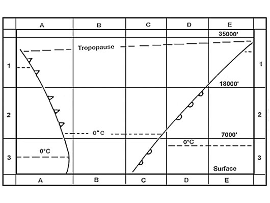
Question 217-12 : At night the ionosphere undergoes changes in ionisation density leading to fluctuations in the strength of received signals in the lfmf frequency band this phenomenon is commonly referred to as ?
Fading caused by the received ground wave and sky wave going out of phase.
Refer to figure night effect the principal propagation method of ndbs is the ground wave however it is possible for weak sky waves to be returned at night when the ionosphere is less dense and attenuation is leastduring the day the d layer of the ionosphere absorbs signals in the lf and mf bands at night the d layer disappears allowing the sky wave to interfere with the surface wave this interference occurs due to the different paths taken by the sky wave and surface wave as well as the induction of currents in the horizontal elements of the loop aerial the contamination effect which is observed as fading of the audio signal and the needle hunting is most pronounced around dawn and dusk when the ionosphere is transitioningat shorter distances 30 to 80 miles the sky waves combine with the ground wave signal without any dead space since the sky waves travel a different path they have a different phase compared to the ground wave as a result the aerial null signal is suppressed or displaced in a random manner leading to wandering of the needle on the rmi or rbi this effect is called fading and is most variable during twilight at dawn and duskAbsorption mostly affects the ground wave and is dependent on the transmission power. fading, caused by the received ground wave and sky wave going in phase. attenuation and its impact are greatest on sky waves with high transmitted frequencies.
Question 217-13 : A tacan tactical air navigation radio aid is a uhf military system that may ?
Be used for range information by civil aircraft.
Learning objective 06202040108 state that military uhf tactical air navigation aid tacan stations may be used for dme informationtacan tactical air navigation systems are military uhf tactical radio aids that can be used by military aircraft with the correct receiver fitted tacans provide military aircraft with magnetic bearing radial and range dme distance information from the station tacan function is similar to vordme function but for military aircraft receivers onlyif a civil aircraft is tuned to a tacan frequency the aircraft will receive range dme distance information only magnetic bearing information radial will not be availableBe used for bearing information by civil aircraft. not be used by civil aircraft. be used for bearing and range information by civil aircraft.
Question 217-14 : When mode c is selected on the aircraft ssr transponder the additional information transmitted is ?
Pressure altitude based on 101325 hpa.
Mode c sends the aircraft's pressure altitude provided by the altitude encoderAltitude based on regional qnh. aircraft height based on sub-scale setting. height based on qfe.
Question 217-15 : The ground secondary surveillance radar ssr equipment incorporates a transmitter and receiver respectively operating in the following frequencies ?
Transmitter 1030 mhz receiver 1090 mhz.
Secondary surveillance radar ssr is a radar system used in air traffic control atc which not only detects and measures the position of aircraft but also requests additional information from the aircraft itself such as its identity and altitudethe interrogation pulses are at one frequency 1030 mhz and the reply pulses are at a different frequency 1090 mhz the target aircraft's transponder replies to signals from an interrogator by transmitting a coded reply signal containing the requested informationTransmitter: 1090 mhz xsxreceiver: 1030 mhz transmitter: 1090 mhz xsxreceiver: 1090 mhz transmitter: 1030 mhz xsxreceiver: 1030 mhz
Question 217-16 : Assuming sufficient transmission power the maximum range of a ground radar with a pulse repetition frequency of 450 pulses per second is given velocity of light is 300 000 kmsecond ?
333 km.
Maximum theoretical range = velocity of light 2 x pulse repetition frequency maximum range = 300000 2 x 450maximum theoretical range = 300000 900maximum theoretical range = 333 km666 km. 1333 km. 150 km.
Question 217-17 : A radio beacon has an operational range of 10 nmby what factor should the transmitter power be increased in order to achieve an operational range of 20 nm ?
Four.
If you double transmitter power you will increase your range by the square root of 2 1414 time the range if you divide 20 nm by square root of 2 = 1414 nmand 1414 by square root of 2 = 10 nmso you have to increase by a factor of fourSix. two. eight.
Question 217-18 : Airborne weather radar systems use a wavelength of approximately 3 cm in order to ?
Detect the larger water droplets.
Transmit at a higher pulse repetition frequency for extended range. obtain optimum use of the cosecant squared beam. detect the smaller cloud formations as well as large.
Question 217-19 : The iso echo facility of an airborne weather radar is provided in order to ?
Detect areas of possible severe turbulence in cloud.
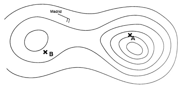
With a monochrome screen it is difficult to distinguish between the severities of turbulent clouds when iso echo is activated a level supplements the automatic gain visual threshold set un weather mode the shap of return on the radar depends upon the gain level of the cloudthe effect is to create a black hole in the cloud by reversing and ampliflying the signal this reversal brings the signal below the automatic gain visual threshold and so no return appears in the middle of the cloud 2612turbulence severity is assessable using the above picture > the hole shows an area of high turbulence > the outer ring shows the severity of the turbulence gradient within the cloud the narrower the retaining ring the steeper the gradient the wider the outer ring the more slack the gradientGive an indication of cloud tops. inhibit unwanted ground returns. extend the mapping range.
Question 217-20 : In the mapping mode the airborne weather radar utilises a ?
Fan shaped beam effective up to a maximum of 50 nm to 60 nm range.
This answer is not accurate today most radars can have a much longer range than that in the mapping mode up to 120 nm boeing 737ng navigation displays map mode 2613Fan shaped beam effective up to a range of 150 nm. pencil beam to a maximum range of 60 nm. pencil beam effective from zero to 150 nm.
Question 217-21 : Which of the following cloud types is most readily detected by airborne weather radar ?
Cumulus.
Cirrocumulus. stratus. altostratus.
Question 217-22 : Why is a secondary radar display screen free of storm clutter ?
The principle of echo return is not used in secondary radar.
The frequencies employed are too high to give returns from moisture sources. a moving target indicator facility suppresses the display of static or near static returns. the frequencies employed are too low to give returns from moisture sources.
Question 217-23 : In order to indicate radio failure the aircraft ssr transponder should be selected to code ?
7600.
7600 radio communication failure7500 unlawful interference with the planned operation of the flight7700 emergency situation7700. 7000. 7500.
Question 217-24 : In order to indicate unlawful interference with the planned operation of the flight the aircraft secondary surveillance radar ssr transponder should be selected to ?
7500.
7600 radio communication failure7500 unlawful interference with the planned operation of the flight7700 emergency situation7600. 7700. 7000.
Question 217-25 : An apparent increase in the transmitted frequency which is proportional to the transmitter velocity will occur when ?
The transmitter moves towards the receiver.
Because the radio signals travel at a constant speed assuming they are not refracted by the atmosphere the receiver can calculate exactly how far away it is from the transmitterspeed is most often calculated by the receiver using the doppler effect which is the process by which the frequency of a signal changes due to the relative motion of the transmitter frequency is raised when the transmitter moves towards the receiverThe transmitter moves away from the receiver. the receiver moves towards the transmitter. both transmitter and receiver move towards each other.
Question 217-26 : A primary radar operates on the principle of ?
Question 217-27 : The main factor that limits the range of an ndb is the ?
Transmitted power.
Height of the transmitter. direction of the plane of polarisation. identification modulation signal.
Question 217-28 : The two main design functions of secondary surveillance radar ssr mode s are ?
Air to ground and ground to air data link communications and improved atc aircraft surveillance capability.
Collision avoidance using tcas ii and improved long range (hf) communication capability. continuous automatic position reporting using global positioning system (gps) satellites and collision avoidance using tcas ii. the elimination of ground to air communications and the introduction of automatic separation between aircraft using tcas ii.
Question 217-29 : A frequency of 10 ghz is considered to be the optimum for use in an airborne weather radar system because ?
The larger water droplets will give good echoes.
A high frequency is used since it gives strong return of echoes from big water droplets and clouds of high water contents usually thunderstorm movements but do not reflect the clouds with lower contents of water or fogGreater detail can be obtained at the more distant ranges of the smaller water droplets. static interference is minimised. enables the aircraft to detect clear air turbulence.
Question 217-30 : Which of the following is a complete list of airborne weather radar antenna stabilisation axes ?
Roll and pitch.
Weather radar antenna in the nose radome of a boeing 757 2547you can clearly see the stabilisation system 2548Roll, pitch and yaw. pitch and yaw. roll and yaw.
Question 217-31 : In an airborne weather radar that has a colour cathode ray tube crt increasing severity of rain and turbulence is generally shown by a change of colour from ?
Green to yellow to red.
2614Yellow to amber to blue. green to red to black. yellow to orange to red.
Question 217-32 : When an aircraft is operating its secondary surveillance radar in mode c an air traffic controller's presentation gives information regarding the aircraft's indicated flight level in increments of ?
100 ft.
Air traffic controller's presentation gives information regarding the aircraft's indicated flight level mode c in increments of 100 ft 2615afr1670 air france 1670 038 3800 ft climbing m15 control sector m15200 ft. 250 ft. 150 ft.
Question 217-33 : A radar facility transmitting at a pulse recurrence frequency prf of 1200 pulsessecond will have a maximum unambiguous range of approximately ?
69 nm.
Maximum range = pulse repetition time 2 x 0162 nmmicrosecond pulse repetition time = 1 x 10⁶ recurrence frequencypulse repetition time = 83333maximum range = 833332 x 0162 = 675nmalso velocity of light = 300000kmsrange = 300000prf x 2range = 3000001200 x 2range = 125km ==> 675nm135 nm. 270 nm. 27 nm.
Question 217-34 : The frequency of an ssr ground transmission is ?
Question 217-35 : The doppler navigation system is based on ?
Radar principles using frequency shift.
Doppler principle the relative motion between transmitter and receiver causes a proportional frequency shift fd which is known as doppler shift doppler effect or doppler frequencytransmitter and receiver are screened from each other but use the same aerial beams are transmitted with a depression angle of 60 and 70 degrees and the receiver measures the reflected frequency shift caused by aircraft's speed along track ground speed speed across track and driftas the transmitter and receiver get closer a positive shift occurs in fd and as they move far apart a negative shift occurs in fdPhase comparison from ground station transmissions. doppler vor (dvor) navigation system. radio waves refraction in the ionosphere.
Question 217-36 : In which mode of operation does the aircraft weather radar use a cosecant radiation pattern ?
Mapping.
boeing 737ng navigation displays in map mode 2613Contour. weather. manual.
Question 217-37 : The main factor which determines the minimum range that can be measured by a pulsed radar is pulse ?
Length.
Pulse length defines the minimum theoretical range of a radarAmplitude. repetition rate. frequency.
Question 217-38 : Complete the following statementaircraft surface movement radar operates on frequencies in the i band employing an antenna that rotates at approximately ii revolutions per minute it is iii possible to determine the type of aircraft from the return on the radar screen ?
I shf ii 60 iii sometimes.
(i) ehf (ii) 30 (iii) never. (i) shf (ii) 10 (iii) always. (i) ehf (ii) 100 (iii) never.
Question 217-39 : The maximum pulse repetition frequency prf that can be used by a primary radar facility in order to detect targets unambiguously at a range of 50 nm is pps = pulses per second ?
1620 pps.
Range = c 2ff pps = c velocity of light 2 x rangerange= 50 nmf = 162000 nms 2 x 50f = 1620 pulses per second3240 pps. 610 pps. 713 pps.
Question 217-40 : Ignoring pulse length and fly back a radar facility designed to have a maximum unambiguous range of 50 km will have a prf pulses per second of ?
3000.
Maximum range = velocity of light x 1 prf50 km = 300000 x 1prfprf = 300000 50 = 6000but we have to ignore pulse length and fly back so 600026000. 167. 330.
Exclusive rights reserved. Reproduction prohibited under penalty of prosecution.